PANAVISION SSR Operation Manual Download Page 7

Panavision SSR manual ---

 5 

V1.0 

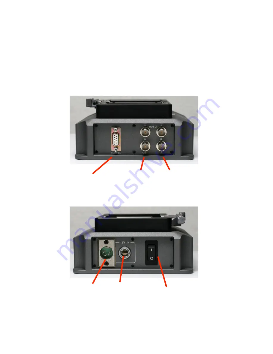
2.1  SSRD Docking Station Connectors 

 
The SSRD is a small docking station for the SSR.  
 
When the SSR is docked to the SSRD, the HD-SDI inputs and outputs are available on BNC 
connectors on the SSRD.  The HD-SDI signal contains embedded audio from the SSR. 
 
A 9-pin D connector on the SSRD allows the SSR to be controlled in slave mode by a serial 
controller implementing the Sony P2 9 pin protocol, just like a Sony videotape recorder. This Sony 
protocol compatibility makes it easy to integrate the SSR into existing post-production facilities 
and workflows. 


The SSRD is provided 12 Volt power via a 4-pin XLR or a 3-pin LEMO connector, which can also 
serve as a loop-through power output.  


A

 & 

Link 

HDSDI


IN

puts 


A

 & 

Link 

HDSDI


OUT

puts 

REMOTE 

RS422 serial control 

Power 

IN

put  

(11 to 17V)  

Power  
alternative 

IN

put 

or loop-through 

output  

Power Switch 

Summary of Contents for SSR

Page 1: ...PANAVISION SSR Operation Manual Advanced Digital Imaging 1st Edition Rev 1 0...

Page 2: ...to be accurate is provided strictly as is and without warranty of any kind including liability or warranties relating to fitness for a particular purpose merchantability or infringement of any patent...

Page 3: ...__________________________ 11 5 0 MENU SYSTEM ___________________________________ 12 5 1 SUB MENUS______________________________________ 13 5 2 SYSTEM MENU ___________________________________ 14 5 3 V...

Page 4: ...ol many functions of the SSR so that the two operate as an integrated package Before starting to use the SSR one of two distinct system modes must be chosen see section 6 Standard Play SP mode allows...

Page 5: ...in down converter for NTSC or PAL output even when mounted on the Genesis The SRW 1 cannot do so when docked to the camera The SSR also provides a HD SDI 422 output for monitoring when mounted on the...

Page 6: ...sm Other possible connections are shown below ACCessory input and output NETWORK at present for use by Panavision service technicians only SD OUT NTSC or PAL composite video output GENlock Tri Level S...

Page 7: ...controlled in slave mode by a serial controller implementing the Sony P2 9 pin protocol just like a Sony videotape recorder This Sony protocol compatibility makes it easy to integrate the SSR into exi...

Page 8: ...g encoder will jog single frames forward and reverse pushing will select input video at the HD outputs and show the timecode generator time TCG With other screens turning the encoder is used to select...

Page 9: ...by the menu system when activated BOTTOM and ICON sections are always displayed When the SSR is docked on top of the Genesis camera use the Display Rotate switch to orient the screen like this BOTTOM...

Page 10: ...ATE switch to change the orientation as depicted below Note that in this position the ICON section is below the BOTTOM section TOP section STATUS error messages Changes with MENU BOTTOM section Big ti...

Page 11: ...first frame of a clip pushing Play F3 starts playback Playback will continue until the end of all recordings is reached or when Stop F4 is pushed You can safely start recording at any time either by p...

Page 12: ...standalone The T character indicates the input status of external time code it will have a green background when the internal timecode is jam synced to the external code MIDDLE section Clip List The C...

Page 13: ...ALT key will display the following alternative functions 4 4 RECORD MODE During recording the SSR position status line will turn red F1 First Clip F2 Last Clip F3 Fast Forward F4 Rewind Select fps va...

Page 14: ...rey rather than white You can navigate the list of menu items by rotating the Encoder thumbwheel The current menu item is highlighted in Blue Push the Encoder thumbwheel to select the current item Pus...

Page 15: ...as been activated To select a sub menu item turn the encoder thumbwheel to highlight the new item and then push the encoder switch To cancel a sub menu selection push the MENU key Certain functions wi...

Page 16: ...U R C E Select INTernal INTernal RTC real time clock EXTernal LTC or EXTernal HDSDI video as the timecode generator source See Appendix B for more information about TC options T C U S E R B I T T C U...

Page 17: ...erial digital interface S D M O D E S D M O D E Select the aspect ratio on the SD OUT BNC next to GEN See section 2 0 Select between Letterbox Edge crop or Squeeze to fit the 16 by 9 frame in the SD s...

Page 18: ...nd incremented with every subsequent recording Position tells you how much you have recorded The Timecode signal is set either internally or externally in the System Menu See section 5 2 Main TC Displ...

Page 19: ...is on the HOME screen when you push the Encoder jog knob to see the EE video signal M a i n T C D i s p M a i n T C D i s p You can select 1 of 4 settings 1 Remaining capacity 2 Position 3 Timecode 4...

Page 20: ...ay Position if it is in AUTO mode and the Clip list will also show Positions C H A R A C T E R S C H A R A C T E R S Select whether to turn characters On or Off in the video monitor 422 output and the...

Page 21: ...nd will be muted Typically you will select CH 1 2 when the SSR is docked on the Genesis camera A u d i o T G A u d i o T G Turn 1KHz audio test signal generator On or Off G a i n C H 1 G a i n C H 2 G...

Page 22: ...the SSR are powered down after the selected elapsed time This achieves significant power savings however there will be a delay of approximately 5 seconds when starting recording or playback I N T E R...

Page 23: ...very time the SSR records a frame it is not an indication of the exact position of the camera exposure Other GPI and GPO options will be included in the future as need arises Note that the Accessory p...

Page 24: ...ALT ENCODER F1 In SP mode both 444 and 422 recording are possible and any recording format may be selected at any time In SP mode you will get approximately 21 minutes of recording time at 24fps 2 LP...

Page 25: ...hnicians may find useful To access Diagnostics push and hold down ALT and then push MENU The above screen shows the SSR firmware version numbers along with the version temperature and status of variou...

Page 26: ...2 earlier HOME screen warnings WARM in yellow then HOT in red The following error codes are less serious but should not be ignored You will be able to continue recording Contact your Panavision repres...

Page 27: ...B preset UB TOD UB ext TC INTERNAL PRESET Free running Preset UB Preset UB Time Of Day UB External UB or Preset UB 1 INTERNAL REGEN Rec Run May be Preset Preset UB Preset UB Time Of Day UB External UB...

Page 28: ...will not convert material if its format setting is incorrect that is if 422 material has been recorded and the SSR system is set to 444 playback will be incorrect Select the correct frame rate on bot...

Page 29: ...for the audio cable Neutrik nanacon NSC3M SSR NETWORK Lemo Connector 4 pin 0 Pin Signal 1 TxConn_N 2 TxConn_P 3 RxConn_N 4 RxConn_P Ethernet cable connections assuming SSR is connected to Ethernet Hub...

Page 30: ...6 7 8 EXT GND The SSR accessory connector provides true optically isolated inputs and outputs EXT VIN should be in the range of 3 to 9v DC A typical example is shown below Pin 1 EXT VIN Pin 4 GPI0 Pin...

Page 31: ...Panavision SSR manual 29 V1 0 SSRD 9 pin REMOTE connector SSRD is wired as a slave controlled device Pin Signal 1 Frame Ground 2 Tx A 3 Rx B 4 Gnd 5 6 Gnd 7 Tx B 8 Rx A 9 Frame Ground...

Page 32: ...1 60 AUDIO CHANNELS 16 from HD SDI signal 2 from Analog inputs CAPACITY 62400 frames in LP mode 4 2 2 only 43 minutes 24 fps 41 minutes 25 fps 34 minutes 30 fps 31200 frames in SP mode 4 4 4 Dual 4 2...

Reviews: