


Panavision SSR manual ---
9
V1.0
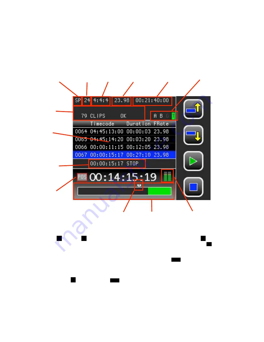
4.2 HOME SCREEN
The home screen shows a lot of information about the current status of the SSR. If errors occur
they are shown in the TOP section with an error code and a brief explanation. Most errors can be
dismissed after the error condition is removed. This is the case, for example, with an error
indicating that recording was attempted in the absence of input video. Critical system errors,
such as hardware failure, will cause a full screen error message to be displayed, and will disable
further recorder operation. (see Appendix A for more information about Error Messages).
Previous recordings are reviewed by using the 4 basic transport controls provided. Pushing the
Previous
F1
and Next
F2
Clip controls jumps to the first frame of a clip, pushing Play
F3
starts
playback. Playback will continue until the end of all recordings is reached or when Stop
F4
is
pushed.
You can safely start recording at any time, either by pushing the SSR
REC
ord key, or by pushing
the Genesis camera record button. This will automatically create a new clip and recording will
start after all existing material. Starting to record will never erase previous recordings.
If you push Play
F3
after pushing the
REC
ord key to stop a recording, the SSR will playback the
last clip from the beginning. This “record review” option, indicated by a highlighting of the play
icon, disappears as soon as you push another button on the SSR.
F1
Previous Clip
F2
Next Clip
F3
Play
F4
Stop
Store Length
Frame rate
Format
Timecode
fps
System Mode
Input Status
Remaining
Capacity
Playback
Position
Sub TC
Display:
Playback
Position
& Status
Main TC
Display type.
Clip List
Status & Error
messages
Analog Audio
input level