


4
---
Panavision SSR manual
V1.0
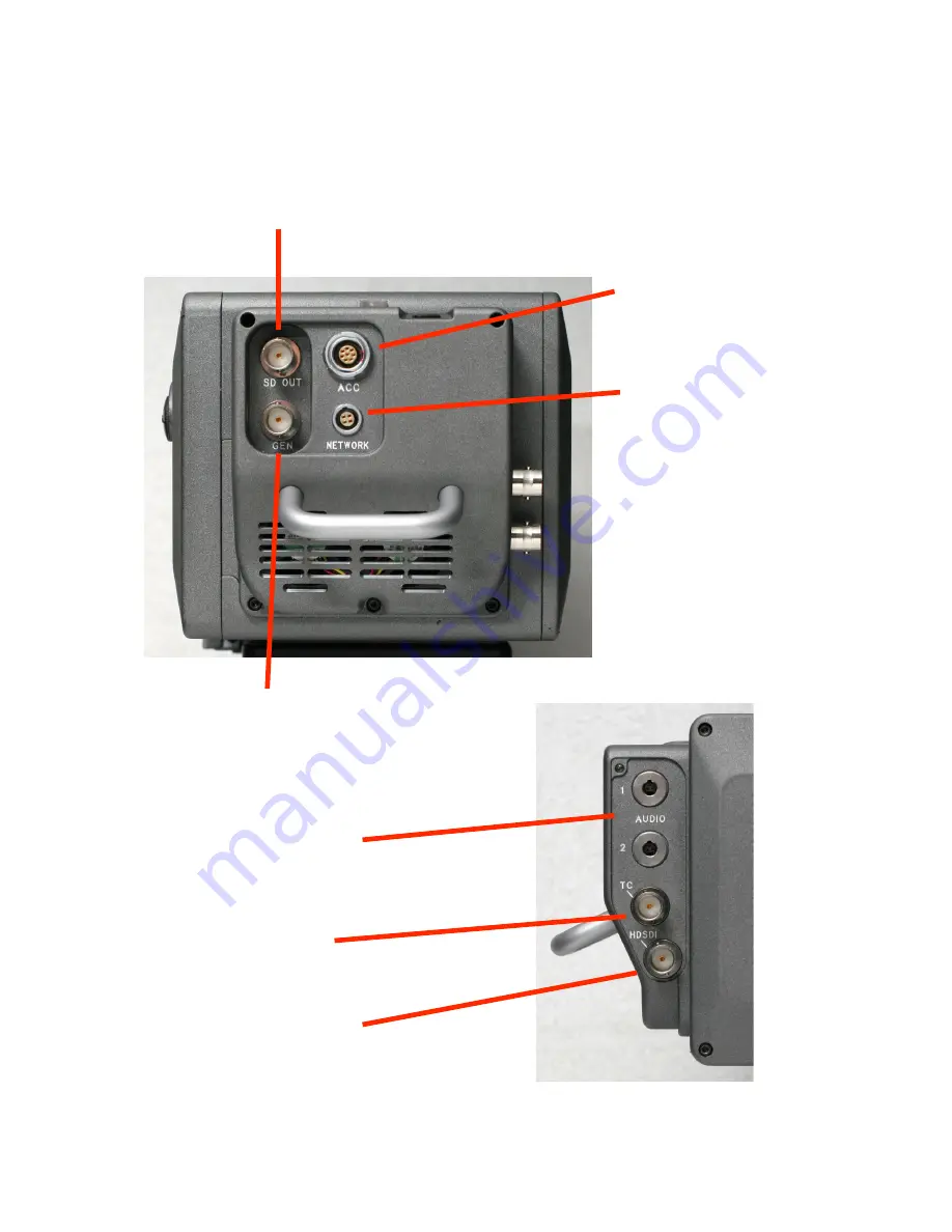
2.0 SSR CONNECTIONS
When the SSR is docked to the Genesis camera, the HD-SDI signal is input via the multi-pin
connector in the docking mechanism. Other possible connections are shown below.
ACC
essory
input and output
NETWORK
at present for use by
Panavision service
technicians only
SD OUT
NTSC or PAL composite video output
GEN
lock
Tri-Level Sync input
can only be used
when SSR is not
docked on camera
HDSDI
422 monitor output
with optional characters
TC
LTC Timecode input
AUDIO
2 analog line-level
audio inputs