3DQDVRQLF
42
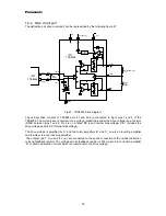
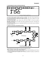
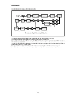
(e) As the output of the 4.3MHz BPF has ANTI-BELL batture, the signal is applied to the 4.3MHz BELL
FILTER to equalize its level and group delay vs frequency. The center frequency of the BELL FILTER
adjusted automatically tin the V-SYNC period based on the crystal frequency. A capacitor connected to
pin 22 is to hold this frequency.
(f) Then equalized signal is applied to the Limiter to define its amplitude and remove noises included.
(g) The output of the Limiter is led to the 1/4 countdown circuit to convert FM center frequency from 4.3MHz
to 1.1 MHz.
(h) The SYNC gate pulse gates the 1.1 MHz FM signal during H-SYNC period to remove noises in the
period.
(i) The 1.1 MHz BPF is the remove highharmonics component which appears on 1/4 countdown.
(j) After BPF, the FM signal is led to the ANTI-BELL to recover ANTI-BELL nature as shown on the original
SECAM chrominance signal. This FILTER is also adjusted automatically in the V-SYNC period, and a
capacitor connected to #18 holds the center frequency of the FITER too.
(k) THE ACC2 regulates output signal level by detecting its IDENT signal level as same as the ACC1.
(l) The ANTI-BELL FILTER makes front and back of the chrominance signal peaky.
(m) The output signal level at #12 is selectable via I
2
C BUS data. In case of the parallel control, the output
level is set to 011 I
2
C BUS data equivalent.


