3DQDVRQLF
12
3. Standard TV-norm: divider ratio 525 (60Hz) or 625 (50Hz)
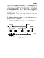
When the system is switched to the narrow window (standard mode) it is checked whether the
incoming vertical sync pulses are according to the TV norm, if so IVW=1. When 15 standard TV-norms
are counted the divider system is switched to the standard divider ratio mode. In this mode the divider
is always reset at the standard value even if the vertical sync pulse is missing.
The system switches back to the narrow window when 3 vertical sync pulses are missed. When also
in the narrow window 3 vertical sync pulses are missed, the divider will switch to the search window
mode.
As described above the vertical divider needs some waiting time before switching back to the search
window mode. When a fast reaction is required for instance during channel switching the system can
be forced to the search window by means of I²C bus, setting NCIN = 1 (vertical divider mode).
Immediate after forcing to search mode NCIN has to be set back to 0 for optimum performance.
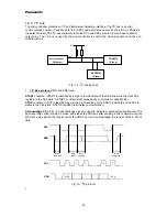
The vertical synchronization mode of operation can be selected by I²C bus FORF/S, forced field
frequency.
Furthermore, 50/60Hz identification is available by I²C bus FSI (50/60Hz), and norm signal
identification with IVW. Interlace can be switched on and off by I²C bus DL.
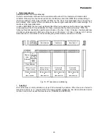
PH
l1
Filter
42
41
40
T
im
in
g
PH
l1
H
out
C
alib
ra
tio
n
H
or
iz
ont
al
Fly
b
ack
in
/
de
te
ct
or
H
or
iz
ont
al
o
scillato
r
PH
l2
de
te
ct
or
Slo
w
sta
rt
&
Sto
p
syste
m
V
ertical
D
iv
id
er
San
d
cas
tle
G
en
erato
r
V
sync
.
sep
ar
atio
n
sep
ar
atio
n
H
sync
.
N
oi
se
de
te
ct
or
C
oi
nc
id
en
ce
de
te
ct
or
B
la
nki
ng
G
en
erato
r
sl
o
w
st
ar
t
&
st
o
p
+
-
6V
H
B
L
, L
B
M
H
O
B
IV
W
F
S
I
H
S
H
F
O
R
F
, F
O
R
S
N
C
IN
, D
L
H
sync
H
sync
F
sc
L
um
a
from
F
ilter
s &
S
w
itch
es
V
er
tical p
u
ls
e
for ge
om
etr
y
S
andc
as
tl
e out
D
ri
v
e
PH
l2
Filter
V
ID
P
O
C
F
O
A
F
O
B
IF
1
43
R
G
B
bl
ank 1
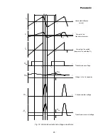
Fig 6 : Block diagram: Horizontal and vertical synchronization


