3DQDVRQLF
11
* H-output and slow start/stop
The horizontal output is the driver pin for the line deflection. It is an open collector output. Under
normal operation condition the duty cycle of the output pulse is 45% off (Hout = high) / 55% on (Hout =
low).
A build in slow start/stop circuit ensures a smooth start/stop behavior of the line deflection and protects
the line output transistor.
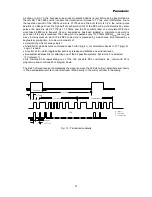
During switch-on the horizontal output starts with the double frequency (31.25 kHz) and with a duty
cycle of 75% off (Hout = high)/ 25% on (Hout = low). After about 50ms the frequency is changed to the
normal value (15.625 kHz) and the duty cycle to 45% off (Hout = high) / 55% on (Hout = low).
Also during switching-off via stand by (STB) the frequency is switched to the double value and the
RGB drive is set to maximum to discharge the voltage on the EHT capacitor to half of its maximum
value. After about 100ms the RGB drive is set to minimum and 50ms later the horizontal drive is
switched-off.
* Noise detector
The TDA8844 has an internal noise detector which is used to switch the time constant of the horizontal
PLL.
The input of the detector is connected to the selected CVBS input.
The noise detector measures the RMS value of the noise during a part of the sync pulse. (The
detection level is 100mVrms and corresponds to 20dB S/N-ratio for 1Vpp CVBS).
A field counter is used for hysteresis and decides after 2 successive fields whether noise is detected.
When noise is detected the horizontal PLL time constant is switched to slow.
* Coincidence detector
The coincidence detector detects whether the incoming CVBS signal is synchronized with the
horizontal oscillator, thus whether the PHI-1 loop is in-lock. The output is available by I²C bus, SL, and
can be used for search tuning and OSD. For out of lock condition the coincidence detector can be
made less sensitive (about 5 dB) by control bit STM (search tuning mode). This prevents false stops.
* Vertical sync separator
The vertical sync separator separates the vertical sync pulse from the composite sync signal. This
separated sync pulse is used to trigger the vertical divider system. To generate a trigger pulse for the
divider the minimum pulse width of the incoming vertical sync pulse must be 17
µ
s.
The integrator network is designed such that for anticopy signals (e.g. Macrovision) with vertical
pulses of 10
µ
s (on) and 22
µ
s (off) still a vertical sync pulse is generated. (Because more lines with
vertical pulses are present, pulse width of less than 17
µ
s is allowed, by integration still the required
level is reached).
* Vertical divider system
The divider system uses a counter that delivers the timing for the vertical ramp generator in the
geometry processor. The clock is derived from the horizontal line oscillator.
The divider system synchronizes on the vertical sync pulse of the vertical sync separator.
The divider has three modes of operation:
1. Search mode (large window)
This mode is activated when the circuit is not synchronized or when a non-standard signal is received.
In the search mode the divider can catch between about 45 and 64.5Hz.
2. Standard mode (narrow window)
This mode is switched on (coming from search mode) when more than 15 successive vertical sync
pulses are detected in the narrow window. When the circuit is in the standard mode and a vertical sync
pulse is missing the retrace of the vertical ramp generator is started at the end of the window (thus
automatic insertion of missing vertical sync pulses). As consequence the disturbance of the picture is
very small. The circuit will switch back to the search window when 6 succeeding vertical periods no
sync pulses are found within the window. (See also NCIN below)
In the narrow window mode the PHI-1 is inhibited during the vertical egalization pulses to prevent
disturbance.


