3DQDVRQLF
34
1.5.2 ABS
operation
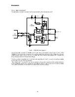
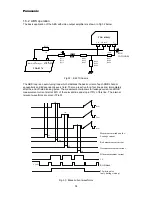
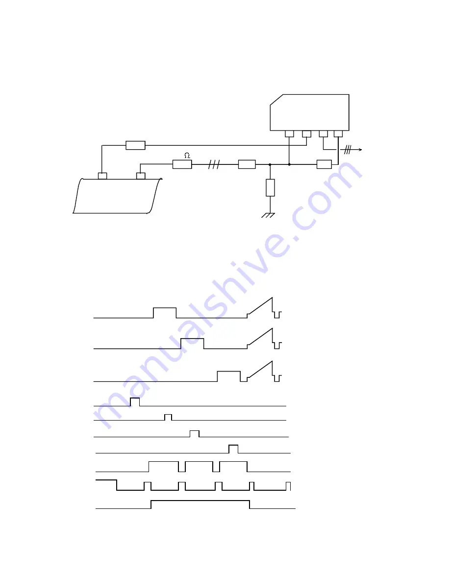
The basic application of the ABS with video output amplifiers is shown in Fig 32 below.
R515
1K
18
19,20,21
RGB outputs
Black current input
TDA 8374
R511
R512
R513
100
R901
R902
R903
R904
R905
R906
100K
R907
R908
R909
3
5
8
9
V
F.B.
Vin
I Black
TDA 6106Q
RGB
CATHODES
Fig 32 : Z-421 Chassis
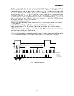
The ABS loop is an auto-tuning loop which stabilizes the back current of each RGB channel
sequentially and independently every field. The loop is active for a four line period, immediately
after the end of field blanking pulse. The measurement windows far leakage current and RGB
measurement current start at 50% of the relevant line and stop at 75% of this line. The internal
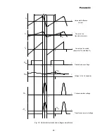
relevant waveforms are given if Fig 33
V pulse
LB
LG
LR
LO
1H
1H
1H
Rout
Gout
Bout
Measurement windows for :
Leakage current
Red measurement current
Green measurement current
Blue measurement current
3L
RGB blank
3L white pulse
(only during start up)
Fig. 33 : Black current waveforms


