background image

51

Full duplex (4 line) 

*

BP 2

BP 1

Function

Switch

position

Function

Switch

position

RS485 Setting

The 4-bit DIP switch in used for
RS485 termination.

ON

Marking

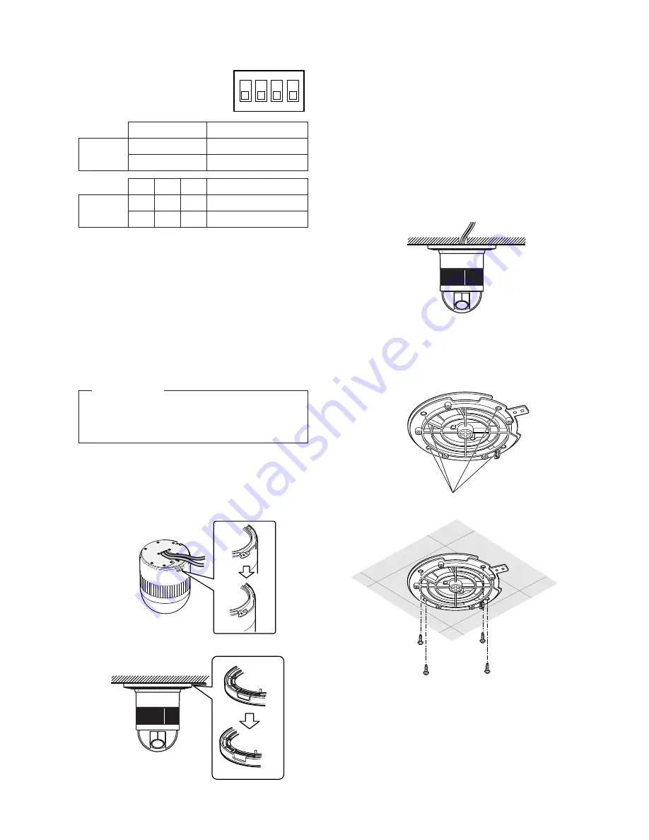
1. Mark the mounting holes on the ceiling,

using the removed camera mounting base
as a template.

2. Fix the camera mounting base to the ceiling

with four screws (not provided, M4).

Note:

Remove sharp edges to protect the

cables.

3. Assemble the Camera

Reverse the disassembly procedure. Take
care not to cut any cables.

OFF

Termination ON

Termination OFF 

*

b. Top Cable Exit

Prepare a hole in the ceiling board to run
the cables.

1

2

3

4

ON

4-bit DIP SW

BP 3 BP 4

ON

ON

ON

OFF OFF OFF

Half duplex (2 line)

Notes:

• Defaults are marked with 

*

.

• BP stands for Bit Position.
• Daisy chain connection is not available for

Full Duplex. (Only for Panasonic’s system
controllers)

Be sure to select a ceiling board strong
enough to support 4 times the total weight of
the camera.

Precaution

a. Sideway Cable Exit

Prepare a cutout in the diecast case and
decoration cover as shown in the following
figures.

Cutout in Diecast Case

Cutout in Decoration Cover

Summary of Contents for WV-CS850A

Page 1: ...connect or operate this product please read these instructions carefully and save this manual for future use Model No WV CS850A WV CS854AE Combination Camera Operating Instructions FRANÇAIS DEUTSCH ENGLISH ESPAÑOL ITALIANO ...

Page 2: ...ndler er i overensstemmelse med den følgende standarder eller andre normative dokumenter i følge bestemmelserne i direktivene 73 23 EEC og 89 336 EEC Vi deklarerar härmed värt fulla ansvar för att den produkt till vilken denna deklaration hänvisar är i överensstämmelse med standarddokument eller andra normativa dokument som framstölls i Direktiv 73 23 EEC och 89 336 EEC Ilmoitamme yksinomaisella v...

Page 3: ...ay 16 Preset 17 Deleting Preset Positions 22 Home Position Setting 22 Self Return Setting 22 Auto Mode Selection 23 AUTO PAN KEY Setting 24 DIGITAL FLIP ON OFF 25 LOCAL REMOTE Setting 25 SPECIAL 1 25 Camera Setting 35 RS485 Setup 46 INSTALLATION 48 CONNECTIONS 53 SYSTEM CONNECTIONS 55 PREVENTION OF BLOOMING AND SMEAR 56 SPECIFICATIONS 56 ACCESSORIES 57 OPTIONAL ACCESSORIES 57 APPENDIX 58 ENGLISH ...

Page 4: ...S485 communications in a com pact enclosure A newly developed 1 4 inch CCD is employed PREFACE for use under extremely low lighting conditions 0 06 lx for monochrome and 1 lx for colour It also assures clear display of pictures in which bright and dark objects coexist without mutual interference thanks to the Super Dynamic2 DSP Setup menus allow the camera to fulfill sur veillance tasks by such me...

Page 5: ...te Take notice of the following cases when uploading the downloaded data to a camera Preset positions may vary If a preset position varies delete the preset position and set the cor rect preset position newly If a preset data of WV CS850A Series is uploaded to lower level models e g WV CS850 Series an error may occur and uploading may not be completed successfully 1 Do not attempt to disassemble t...

Page 6: ...rce ratings Do not use the camera in an extreme envi ronment where high temperature or high humidity exists Do not place near heat sources such as radiators stoves or other units that produce heat Use the camera under conditions where temperature is between 10 C 50 C 14 F 122 F Recommended temperature 40 C 104 F and humidity is below 90 The input power source is 220 V 240 V AC for WV CS850A 24 V A...

Page 7: ...Fall Prevention Wire o Decoration Cover 0 Dome Cover q Alarm Input Connector w Alarm Output Connector e Video Output Connector r Data Port t Power Cable for WV CS850A t Power Cable for WV CS854AE CONSTRUCTION w e r t t q y u o i 0 WV CS850A WV CS854AE ...

Page 8: ... Image Hold ON OFF EL Zoom ON OFF Alarm IN OUT Setting Password Registration Password Verification Cleaning Display Cleaning ON OFF Learning Display Patrol Learn Play Stop Zone Parameter Setting Zone Number Selection Privacy Zone ON OFF Propo P T ON OFF Password Lock ON OFF Direction Setting Area Title Display Area Title Editing Alarm IN OUT Area Title Selection Auto Mode Selection Special 1 Posit...

Page 9: ...P PATROL PAY PROGRAM PRESET CAMERA FUNCTION SERUP ESC HOME SET PRESET WIDE TELE NEAR AUX1 B W AUTO WIPER AUX2 DEF UP DOWN L FAR FOCUS IRIS CLOSS OPEN PROGRAM ALARM IRIS RESET AUTO FOCUS Left Switch Right Switch Down Switch Function Controller WV CU550B WV CU360 WV CU161 WV RM70 Open CAM SETUP See page 16 CAM SETUP key for 2 sec onds or more CAMERA SETUP key for 2 seco nds or more See page 16 Close...

Page 10: ...ored in the files See page 21 for the setting Home Position HOME POSITION HOME POSITION is the camera s basic position It returns to this position automatically when a specific time has elapsed after a manual operation This setting functions only when AUTO MODE is OFF See page 22 for the setting Self Return SELF RETURN SELF RETURN is the time out parameter for returning to the home position The ca...

Page 11: ...is setting Up to 8 zones can be registered Submenus are provided for zone number selection and for parame ter setting See page 25 for details 2 Proportional Pan Tilt Speed ON OFF PROPO P T If ON is selected the zoom ratio changes corresponding to pan tilt speed For example pan tilt speed slows down with zoom in See page 27 for details 3 Area Title ON NESW ON USER OFF Up to 8 area titles can be add...

Page 12: ...er to have the camera ID dis played on the monitor screen or not See page 35 for the setting 2 Light Control ALC MANUAL You can select the mode for adjusting the lens iris The modes are as follows ALC The lens iris is automatically adjusted according to the brightness of the object You can select one of two modes SUPER D2 ON or SUPER D2 OFF MANUAL The lens iris is fixed at the value that you have ...

Page 13: ...ds x16 or 1 1 6 seconds x32 See page 38 for the setting There are two modes for SENS UP as follows AUTO If you select x32 for example the sensitivity is raised automatically to x32 max FIX If you select x32 for example the sensitivity is raised to just x32 Notes Moving objects will appear blurred when shot during the electronic sensitivity enhancement mode since SENS UP is equivalent to setting th...

Page 14: ...s the motion it supplies the alarm signal to the external equipment and stops at its position for the preset DWELL time See page 42 for the setting 9 Auto Focus AF MODE The camera adjusts the focus automatically to the best position by sensing sharpness in the centre area of the picture S M and L stand for the breadth of the sensing area Small Middle and Large See page 43 for details MANUAL S M L ...

Page 15: ...A SETUP key for 2 seconds or more to open the SETUP menu WV RM70 1 Turn the MODE SELECTION switch to the NORMAL or ALARM OFF position 2 Press the PROG switch for 2 seconds or more to open the Program menu 3 Move the cursor to Camera Set Up then press the SET switch to open the SETUP menu Submenu Display The items marked can be selected changed on the submenu Move the cursor to an item with the mar...

Page 16: ... and press the CAM SET key The position setting menu is displayed 2 To Set Panning Tilting Positions 1 Move the cursor to PUSH SET next to PAN TILT and press the CAM SET key The PAN TILT setting menu appears 2 Select panning tilting positions by moving the joystick up and down right and left and press the CAM SET key The positions are set and the screen returns to the position setting menu SET UP ...

Page 17: ...4 To Set the Lens Zoom and Focus Positions 1 Move the cursor to PUSH SET next to ZOOM FOCUS and press the CAM SET key The ZOOM FOCUS setting menu appears 2 Select a zoom position by moving the zoom control up and down and a focus position by moving the focus control up and down and then press the CAM SET key The positions are set and the screen returns to the position setting menu Notes When the c...

Page 18: ... preceding the one currently displayed 2 Display the most prospective ID 3 Follow the step To change an entered PRESET ID if neces sary To Change an Entered PRESET ID 1 Move the pointer to the character to be edited in the editing area by using the joystick and press the CAM SET key 2 Select a new character by using the joystick 3 Press the CAM SET key to determine the PRESET ID To Delete an Enter...

Page 19: ...AL and select ALC or MANUAL by moving the joystick to the right or left ALC The lens iris is automatically adjusted to suit the brightness of the object MANUAL The lens iris is fixed at the set value regardless of the brightness of the object 2 In case of ALC Press the CAM SET key The backlight compensation menu appears in the display See page 36 for the setting 3 In case of MANUAL Press the CAM S...

Page 20: ...R SET Menu Move the cursor to RET and press the CAM SET key The PRE SET NUMBER SET menu appears with the mark on the right of the preset position number To Return to the Setup Menu Move the cursor to RET and press the CAM SET key 2S 3S 5S 10S 30S 1MIN 2MIN 3MIN 4MIN SCENE FILE 1 SHUTTER AGC SENS UP WHITE BAL MOTION DET AF MODE RET OFF ON MID OFF ATW OFF MANUAL M Scene file setting menu PRESET NO 1...

Page 21: ...position Move the cursor to SELF RETURN and select a return time by moving the joystick to the right or left Return time changes as fol lows 2MIN 3MIN 5MIN 10MIN 60MIN 30MIN 20MIN 1MIN OFF MIN stands for minute s Note The camera will return to the AUTO MODE if that is set to SEQ SORT AUTO PAN or PATROL when a specific time has elapsed after a manual operation PRESET NO 1 POSITION SET PRESET ID ALC...

Page 22: ... range is changed after the camera has not panned for a long time or has been panning in the same panning range the picture may not be clear or noise may appear In this case pan the camera fully several times If this does not eliminate the problem refer servicing to qualified service personnel 5 To set pan limit ON OFF Move the cursor to PAN LIMIT and select ON or OFF by moving the joystick to the...

Page 23: ...t When 0S is selected the camera stops without dwelling and starts Auto refreshing may be activated during PATROL PLAY or AUTO MODE to calibrate the lens position AUTO PAN KEY Setting This is to assign one of following auto function to the AUTO key on the controller Pressing the AUTO key activates the assigned function after this setting Move the cursor to AUTO PAN KEY and select an auto function ...

Page 24: ...LOCAL REMOTE and move the joystick to the right or left You can toggle between LOCAL and REMOTE Note REMOTE does not work when the WV RM70 WV CU360 WV CU161 or WJ FS616 is connected Make sure that LOCAL is selected in this case SPECIAL 1 Privacy Zone ON OFF PRIVACY ZONE Up to 8 unwanted zones can be masked on the monitor screen 1 Move the cursor to PRIVACY ZONE and then select ON ENB or OFF ENB by...

Page 25: ...ne then press the CAM SET key 3 2 Move the joystick to adjust the pan and tilt position so that the desired position comes into the zone frame Note Zone setting is not available while the zone frame disap pears for example the camera directs further downward from the 45 position 3 3 Move the cursor to PUSH SET on the ZOOM FOCUS then press the CAM SET key 3 4 Adjust zoom and focus then press the CA...

Page 26: ...N NESW An area title is displayed indicating the camera direction North N North East NE East E South East SE South S South West SW West W and North West NW ON USER A user customized area title is displayed with a maxi mum of 16 characters OFF Area tittle is not displayed Default ON USER 2 Press the CAM SET key A submenu appears except when OFF is selected Settings for ON NESW 1 Move the cursor to ...

Page 27: ... display position in the as same way as AREA TITLE DIRECTION NESW See page 27 3 To add a user customized title move the cursor to the title of the desired number then press the CAM SET key AREA TITLE menu of the selected number appears AREA TITLE Editing 1 Move the cursor to the desired character in the character field using the joystick then press the CAM SET key 2 The selected character appears ...

Page 28: ...ARN set the following parameters for the starting position These parameters are stored when PATROL LEARN mode starts PAN TILT ZOOM FOCUS settings IRIS setting SHUTTER setting AGC setting SENS UP setting WHITE BALANCE setting IMAGE HOLD setting AREA TITLE setting DIGITAL FLIP setting PRIVACY ZONE setting CAMERA ID setting PROPO PT setting PAN LIMIT setting BURST setting CLEANING setting After start...

Page 29: ...P key to stop playback or press any manual operation key e g PAN TILT ZOOM FOCUS except the iris keys PATROL PLAY with a Controller not Having PATROL Key 1 Close the SET UP or SPECIAL 1 menu The camera turns to the starting point and the operations stored in the memory are reproduced Iris operation only is accepted during playback 2 Open the SET UP menu or press any manual operation key e g PAN TI...

Page 30: ...L 1 PRIVACY ZONE PROPO P T AREA TITLE PATROL ALARM IN OUT PASSWORD LOCK CLEANING EL ZOOM PRESET ALM IMAGE HOLD OFF RET OFF ENB ON ON USER STOP OFF OFF ON OFF Special 1 menu ALARM IN OUT ALARM IN 1 ALARM IN 2 ALARM IN 3 ALARM IN 4 CNT CLS 1 TIME OUT CNT CLS 2 COAX ALM OUT RET OFF OFF OFF OFF OFF 100MS OFF OFF ALARM I O submenu CNT CLS 1 2 Output Two contact closure signals Open collector type are o...

Page 31: ...word verification OFF Access to the privacy zone settings is free ENB follows after ON or OFF of PRIVACY ZONE on the SPECIAL 1 menu ON Access is limited by the verification menu DIS follows ON or OFF of PRIVACY ZONE on the SPECIAL 1 menu 2 Press the CAM SET key PASSWORD VERIFICATION 3 The password verification menu appears 3 1 Select a numeral for the first digit by moving the joystick to the righ...

Page 32: ...PE CIAL 1 4 5 Retry step 4 1 to 4 4 If the first entry for the password is dif ferent from the second one the screen returns to the NEW PASSWORD menu 4 6 To return to the SPECIAL 1 menu without changing the pass word move the cursor to RET then press the CAM SET key Cleaning ON OFF CLEANING ON OFF CLEANING Built in electric mechanical contacts are refreshed at regular inter vals approx 7 days if C...

Page 33: ...and Positioning to the designated point is completed for ALARM IN OUT Positioning to the start point is completed for AUTO PAN Positioning to the start point is completed for PATROL PLAY OFF Alarm signals are not output Note Select OFF when the camera downloads or uploads the preset data Image Hold ON OFF IMAGE HOLD ON OFF The camera picture remains as a still image on the monitor until the camera...

Page 34: ... position of the CAMERA ID on the monitor screen Press the MON ESC key to fix the posi tion and return to the character editing menu Notes When you want the pointer to move to a specific character in the editing area select a new character and press the CAM SET key This function allows you to edit or correct a specif ic character When you want a blank space in the CAMERA ID move the character curs...

Page 35: ...creen If necessary refer to Setup Menu Display on page 16 for details on displaying the SET UP on the monitor screen 2 Move the cursor to ALC MANUAL and select ALC or MANUAL by using the joystick When you select ALC set backlight compen sation Note The backlight compensation submenu associated with this menu is described separately and should be set up after installing the camera at the site and o...

Page 36: ...d area move the cursor to that area then press the CAM SET key To cancel all masking area press the F2 button of the WV CU550B For the WV RM70 press the right and left switches simultaneously 5 After masking is completed press the MON ESC key The 48 mask areas on the monitor screen disappear and the field setup menu appears 6 If you want to change the video output level picture contrast move the I...

Page 37: ...unction is enabled afterimages may be produced by shooting a moving object or by panning or tilting the camera For more information refer to digital noise reduction mode selec tion see page 45 6 Electronic Sensitivity Enhancement Setting SENS UP 1 Display SET UP on the monitor screen If necessary refer to Setup Menu Display on page 16 for details on displaying the SET UP menu on the monitor screen...

Page 38: ...witched to the multi plexed vertical drive VD2 regardless which sync mode is select ed Line lock Sync Mode LL 1 Display SET UP on the monitor screen Refer to Setup Menu Display on page 16 for details on displaying the SET UP menu on the monitor screen 2 Move the cursor to SYNC and select LL by using the joystick LL sync mode is not available when the multiplexed vertical drive VD2 pulse is supplie...

Page 39: ...ase of the camera video output signal may be disturbed 8 White Balance Setting WHITE BAL 1 Auto Tracing White Balance Mode ATW 1 Display SET UP on the monitor screen Refer to Setup Menu Display on page 16 for details on displaying the SET UP menu on the monitor screen 2 Move the cursor to WHITE BAL and select ATW by using the joy stick The white balance of the camera is automatically set 3 For fin...

Page 40: ...djustment menu on the monitor screen 6 Move the cursor to R Use the joystick to obtain the optimum amount of red gain The I cursor moves to the right or left 7 Move the cursor to B Use the joystick to obtain the optimum amount of blue gain The I cursor moves to the right or left 8 Move the cursor to RET by using the joystick and press the CAM SET key to return to SET UP AWC R B RET AWC fine adjust...

Page 41: ...larm signal is supplied while the DISPLAY MODE is activated OFF The alarm signal is not supplied while the DISPLAY MODE is activated 7 Move the cursor to DISPLAY MODE Press the CAM SET key to see the present setting The areas that detect the motions start blinking 8 Move the cursor to LEVEL by using the joystick Use the joystick to obtain the optimum detection level The I cursor moves to the right...

Page 42: ...e by moving the joystick to the right or left S M and L stand for Small Middle and Large areas in the centre of a scene that are used for sensing sharpness in auto focusing MANUAL S M L Brings the camera into focus when the AF key on the controller is pressed AUTO S M L Brings the camera into focus while operating pan tilt or zoom manually These may be selected in the same way as selecting MANUAL ...

Page 43: ... the aperture level with the joystick The I cursor moves to the right sharp or left soft To reset to the factory setup press the F2 button of the WV CU550B For the WV RM70 keep pressing the Right and Left switches simultaneously for 2 seconds or more 3 Pedestal Level Setting PEDESTAL 1 Move the cursor to PEDESTAL The I cursor is highlighted 2 While observing the waveform monitor oscilloscope or vi...

Page 44: ... Camera Resetting Move the cursor to CAMERA RESET by using the joystick and press the F3 button of the WV CU550B The camera is reset to the factory preset parameters For the WV RM70 keep pressing the Right Left and Set switch es simultaneously for 2 seconds or more For the WV CU360 or WV CU161 keep pressing the Right and Left switches and the numeric button 5 simultaneously for 2 seconds or more 9...

Page 45: ...BER Displays the unit number set by the DIP switch If the switch is set to 1 96 select a number by moving the joystick to the right or left In an RS485 chain each unit must have a unique number Default 1 See INSTALLATION for DIP switch setting SUB ADDRESS Do not set BAUD RATE Specifies the transmission speed 2 400 4 800 9 600 19 200 bit per second for the RS485 communica tion The factory setting i...

Page 46: ...least 5 seconds DELAY TIME Specifies the time to transmit the acknowledge request when communicating on a 2 line connection OFF 10 20 40 100 ms Default OFF This menu appears only when a 2 line communication is used Make sure to be 100 ms when connecting the camera with the WJ FS616 Video Multiplexer or Matrix Switcher WJ SX350 in a 2 line communication system The settings become effective with the...

Page 47: ...lects termination ON OFF and half full duplex selection for RS485 communications Switch settings are read in to the camera when the power is turned on Make sure to turn it off then turn it back on after changing the switch settings Switch positions and functions are shown below RS485 Parameter Setup The selected protocol communication para meters and set unit numbers are read into the camera when ...

Page 48: ... 3 4 ON 5 6 7 8 1 2 3 4 ON 5 6 7 8 1 2 3 4 ON 5 6 7 8 1 2 3 4 ON 5 6 7 8 Switch position Unit number Switch position Unit number 1 96 1 2 3 4 5 6 7 8 9 10 11 12 13 14 15 16 17 18 19 20 21 22 23 24 25 26 27 28 29 30 31 32 33 34 35 36 37 38 39 40 41 42 43 44 45 46 47 48 49 50 51 52 53 54 55 56 57 58 59 60 61 62 63 64 65 66 67 68 1 2 3 4 ON 5 6 7 8 1 2 3 4 ON 5 6 7 8 1 2 3 4 ON 5 6 7 8 1 2 3 4 ON 5 6...

Page 49: ... 1 2 3 4 ON 5 6 7 8 1 2 3 4 ON 5 6 7 8 1 2 3 4 ON 5 6 7 8 1 2 3 4 ON 5 6 7 8 1 2 3 4 ON 5 6 7 8 1 2 3 4 ON 5 6 7 8 1 2 3 4 ON 5 6 7 8 Switch position Unit number Switch position Unit number 69 70 71 72 73 74 75 76 77 78 79 80 81 82 83 84 85 86 87 88 89 90 91 92 93 94 95 1 2 3 4 ON 5 6 7 8 1 2 3 4 ON 5 6 7 8 1 2 3 4 ON 5 6 7 8 1 2 3 4 ON 5 6 7 8 1 2 3 4 ON 5 6 7 8 1 2 3 4 ON 5 6 7 8 1 2 3 4 ON 5 6 ...

Page 50: ...ake care not to cut any cables OFF Termination ON Termination OFF b Top Cable Exit Prepare a hole in the ceiling board to run the cables 1 2 3 4 ON 4 bit DIP SW BP 3 BP 4 ON ON ON OFF OFF OFF Half duplex 2 line Notes Defaults are marked with BP stands for Bit Position Daisy chain connection is not available for Full Duplex Only for Panasonic s system controllers Be sure to select a ceiling board s...

Page 51: ...the decoration cover against the cam era mounting base 15 Be sure to match the wire with the fall prevention wire fixing angle as shown below Fall prevention wire fixing angle Ring of the fall prevention wire Cautions Use the supplied dust protection sheet if the camera mounting base is liable to be exposed to a dusty atmosphere Remove the cover from the dust protection sheet then stick the sheet ...

Page 52: ... the cable entry seal until it has been ascertained that the unit is functioning CONNECT THIS TO 24 V AC CLASS 2 POWER SUPPLY ONLY Contact Insert Up A Approx 3 mm 0 1 inch Insert the wire until A position and clamp the contacts Wire Up Wire Contact Up Contact Wire Approx 3 mm 0 1 inch Insert the wire until A position and clamp the contacts 1 3 2 4 24 V AC Power Supply Connection CAUTIONS Note When...

Page 53: ...cations are low active non voltage contact ON when active or open collector Low when active The table below shows wire colours versus pin functions GND Brown Red Data transmission Data reception Orange Yellow Green T B T A R B R A Note Use a relay if the voltage or current of the connected device exceeds the ratings ALARM OUT Connections Connect an external device for example a buzzer or lamp to t...

Page 54: ... System Controller WV CU 550 550B LEFT RIGHT UP DOWN ALARM BUSY F3 F4 F2 F1 AF 1 2 3 4 5 6 7 8 9 MON CAM ESC SET 0 ACK RESET BACK SEQ FORWARD SEQ ALT DEC 1CAM INC 1CAM STOP 1 2 AUX CLOSE OPEN IRIS PRESET FOCUS NEAR ZOOM TELE FAR WIDE System Controller WV CU 550 550B LEFT RIGHT UP DOWN ALARM BUSY F3 F4 F2 F1 AF 1 2 3 4 5 6 7 8 9 MON CAM ESC SET 0 ACK RESET BACK SEQ FORWARD SEQ ALT DEC 1CAM INC 1CAM...

Page 55: ...22 digital zoom x10 internal line lock multiplexed vertical drive VD2 50 00 Hz 1 0 V p p PAL composite 75 Ω more than 480 lines at centre C L 570 lines at centre B W more than 400 lines at centre 50 dB AGC OFF weight on 1 lx 0 1 foot candle C L 0 06 lx 0 006 foot candle B W at SENS UP x 2 AGC HIGH approx 4 5 s TELE WIDE in manual mode approx 5 s FAR NEAR in manual mode automatic open close is poss...

Page 56: ...Decoration cover 1 pc Alarm in cable 1 pc Alarm out cable 1 pc Connector for 24 V AC only for WV CS854AE 1 pc MANUAL AUTO OFF SEQ SORT AUTO PAN PATROL SEQ SORT AUTO PAN PATROL PLAY ON OFF preset ID camera ID area title up to 16 characters ON OFF ON OFF 4 inputs ALARM IN 1 4 2 outputs ALARM AUX1 B W AUX2 AUTO ON OFF ON OFF up to 8 zones ON OFF LEARN PLAY STOP up to 30 seconds ON OFF AUTO MODE AUTO ...

Page 57: ...UNC Close 1 7 0 CAM FUNC EL SHUTTER On 1 7 1 CAM FUNC Off 1 7 2 CAM FUNC Speed Up 1 7 3 CAM FUNC Speed Down 1 7 4 CAM FUNC AGC On 1 7 5 CAM FUNC Off 1 7 6 CAM FUNC SENS UP On 1 7 7 CAM FUNC Off 1 7 8 CAM FUNC Up 1 7 9 CAM FUNC Down 1 8 0 CAM FUNC SENS UP AUTO On 1 8 1 CAM FUNC Off 1 8 2 CAM FUNC Up 1 8 3 CAM FUNC Down 1 8 4 CAM FUNC LL SYNC phase INC 1 8 5 CAM FUNC DEC 1 8 6 CAM FUNC PAN 180 turn ...

Page 58: ...n Japan N 19 Gedruckt in Japan Imprimé au Japon Impreso en Japón Stampato in Giappone 2001 Matsushita Communication Industrial Co Ltd All rights reserved Matsushita Electric Industrial Co Ltd Web Site http www panasonic co jp global ...

Reviews: