background image

11

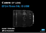
Screen when "SCENE1" is selected

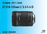
Screen when "SCENE2" is selected
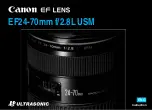
    **CAMERA SETUP** 

SCENE1

 ALC/ELC    ALC    

 SHUTTER    OFF

 AGC        ON(HIGH)

 SENS UP    OFF

 WHITE BAL  ATW1

 DNR        HIGH

     AUTO1

 VMD        OFF

 RET TOP END

D&N(IR)

    **CAMERA SETUP** 

SCENE2

COPY(SCENE1)

 ALC/ELC    ALC    

 SHUTTER    OFF

 AGC        ON(HIGH)

 SENS UP    OFF

 WHITE BAL  ATW1

 DNR        HIGH

     AUTO1

 VMD        OFF

 RET TOP END

D&N(IR)

CP600

Camera operation setting [CAMERA SETUP]

The following describes the camera operation settings. The following settings can be configured on the “CAMERA SETUP”
screen displayed from the top screen. 
Refer to page 5 for how to call up the screen. 
The settings configured on the “CAMERA SETUP” screen will be saved as a scene file. 

1. Register a scene file [SCENE1/SCENE2]

It is possible to register 2 patterns of scene file. When different settings are to be applied between day and night, SCENE1 can be 
applied in the daytime and SCENE2 at night. Change between the scene files can be made by shortcut operation. (

 page 28)

“SCENE1” is set as the default setting. 

Step 1

After confirming that “SCENE1” is selected, configure the settings of “ALC/ELC” through “VMD”. (

 page 11-19) 

To change the scene files, go to step 2. 

Step 2

Move the cursor to “SCENE1” and press the [RIghT] or [LEfT] button to select “SCENE2”. 

 The screen changes and displays “SCENE2”. 

Step 3

To configure the settings of “SCENE2” using the settings of “SCENE1”, press the [SET] button after moving the cursor to 
“COPY(SCENE1)”. 

 The settings of “SCENE1” will be copied to “SCENE2”.

Step 4

Edit the settings to be changed as the settings of “SCENE2”. 
The number displayed at the right side of the title on each setting screen indicates a scene 
file number. 

Step 5

Move the cursor to “SCENE2” and press the [RIghT] or [LEfT] button to select “SCENE1” 
to resume normal operation.

Important:

•  

CP620


CP600

 When “ALARM IN” is set to “SCENE 2” (

 page 20), then “SCENE X (EXT)” will display and cannot be changed.

* X is either “1” or “2”. 

2. Light quantity control method selection [ALC/ELC] 

The method of controlling the quantity of light is selected from the following in accordance with the lens to be used. 

ALC

 (default)

The iris of the lens is automatically adjusted in accordance with the brightness of a subject. Select “ALC” when using 
an ALC lens. 

ALC+: 

Controls the quantity of light with a combination of the electronic shutter and auto iris. This selection is suitable at shooting 

a bright subject such as an outdoor subject with auto iris lens. Be aware that flicker may occur when a subject is under 
fluorescent lighting. 

ELC: 

Controls the quantity of light with the electronic shutter. This selection is suitable for use of a lens with fixed iris or manual iris.
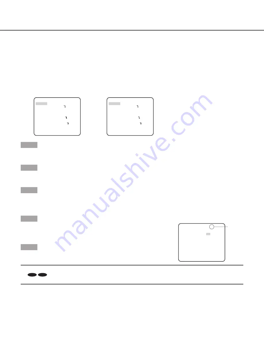
Scene file 

number

   **ALC CONT**(1)

              -     +

.I..... 0

“ALC CONT” screen

BACK LIGHT COMP

SUPER-D6      ON

LEVEL

RET TOP END

Summary of Contents for WV-CP620/G Series

Page 1: ...mber is abbreviated in some descriptions in this manual Operating Instructions Color CCTV Camera Model No WV CP600 G Series WV CF614E Series Lens is optional for WV CP600 G Series W V CP600 WV CP600 G...

Page 2: ...rks Adobe Acrobat Reader and Reader are either registered trademarks or trademarks of Adobe Systems Incorporated in the United States and or other countries About notations The following notations are...

Page 3: ...ge detection 19 Camera system setting SYSTEM SETUP 20 10 Synchronization method SYNC 20 11 Alarm input output terminal setting ALARM IN OUT 20 Configure the alarm input terminal settings 20 Configure...

Page 4: ...e SYNC Only INT method can be used ALARM IN OUT CP620 CP600 Performs the settings of the alarm input output terminal PRIVACY ZONE Hides undesired portions in the camera shooting area STABILIZER Decide...

Page 5: ...nshot 3 The selected setup screen in the setup menu appears on the screen Note If the top screen of the setup menu is called up with the operation buttons while the camera is operated the setup mode i...

Page 6: ...END CAMERA ID 0123456789 ABCDEFGHIJKLM NOPQRSTUVWXYZ SPACE POSI RET TOP END RESET SYSTEM SETUP SYNC INT PRIVACY ZONE OFF STABILIZER OFF EL ZOOM OFF UPSIDE DOWN OFF LDC I 0 RET TOP END SPECIAL SETUP C...

Page 7: ...P END CAMERA ID 0123456789 ABCDEFGHIJKLM NOPQRSTUVWXYZ SPACE POSI RET TOP END RESET SYSTEM SETUP SYNC INT PRIVACY ZONE OFF ALARM IN OUT STABILIZER OFF EL ZOOM OFF UPSIDE DOWN OFF LDC I 0 RET TOP END S...

Page 8: ...OFF STABILIZER OFF EL ZOOM OFF UPSIDE DOWN OFF LDC I 0 RET TOP END SPECIAL SETUP screen LANGUAGE SETUP screen LANGUAGE SETUP LANGUAGE ENGLISH SET RET TOP END SPECIAL SETUP CHROMA GAIN I 160 AP GAIN I...

Page 9: ...Y ZONE OFF STABILIZER OFF EL ZOOM OFF UPSIDE DOWN OFF LDC I 0 RET TOP END SPECIAL SETUP screen LANGUAGE SETUP screen LANGUAGE SETUP LANGUAGE ENGLISH SET RET TOP END SPECIAL SETUP CHROMA GAIN I 160 AP...

Page 10: ...haracter The entered characters are displayed in the editing area Character entry To revise a character move the arrow in the editing area to a wrong character with use of the RIGHT or LEFT button and...

Page 11: ...splays SCENE2 Step 3 To configure the settings of SCENE2 using the settings of SCENE1 press the SET button after moving the cursor to COPY SCENE1 The settings of SCENE1 will be copied to SCENE2 Step 4...

Page 12: ...ELC or ALC and the SET button is pressed the ELC CONT or ALC CONT screen will appear When ELC or ALC is selected the SUPER D6 function is disabled appears and OFF is selected Go to Step 3 Step 2 Move...

Page 13: ...0 1 10000 1 120000 Note When ALC ELC is set to ELC or ALC appears and the shutter function cannot be activated 4 Gain control setting AGC Select a gain control setting from the following ON HIGH defau...

Page 14: ...of the color temperature ranges from 2000 K to 10000 K When AWC is selected the white balance needs to be adjusted Note If the situation meets one of the followings color may not be accurately reprod...

Page 15: ...e color becomes lighter Step 3 Move the cursor to AREA and press the SET button to enter AREA setting screen The area to detect white area of white balance can be set on the area setting screen The ar...

Page 16: ...ness is merely determined by information from the CCD image sensor When AUTO2 is selected the wave length of the light source shall be 800 nm or longer CP600 CF614 Cannot set the switching brightness...

Page 17: ...ving straight at the camera The subject is moving too fast or too slow The subject is too small or too large There are too many moving objects Light reflected through a window or from a road surface T...

Page 18: ...ons may be confirmed through the motion detection mode when a moving object is detected OFF default Does not output alarm signal when in display mode Step 5 Move the cursor to DISPLAY MODE and press t...

Page 19: ...the camera direction largely Follow the procedure below CAMERA SETUP screen VMD SCENE CHANGE CAMERA SETUP SCENE1 ALC ELC ALC SHUTTER OFF AGC ON HIGH SENS UP OFF WHITE BAL ATW1 DNR HIGH AUTO1 RET TOP...

Page 20: ...ET TOP END ALARM IN OUT screen ALARM IN OUT ALARM IN OFF ALARM OUT OFF RET TOP END Move the cursor to ALARM IN OUT and press the SET button The ALARM IN OUT screen appears Step 2 Move the cursor to AL...

Page 21: ...minal while an image is displayed in the black and white mode 12 Privacy zone setting PRIVACY ZONE When undesired portions in the camera shooting area on the screen exist those portions privacy zone c...

Page 22: ...the image stabilizer OFF default Disables the image stabilizer Important When ON is selected for the image stabilizer the view angle becomes narrower and the resolution becomes lower When ON is select...

Page 23: ...ting screen appears Step 5 Press the up down right and left buttons to determine the position of the area to be set and press the SET button The position can be changed in the range of zoom factor set...

Page 24: ...justing the back focus either automatically ABF or manually Important The auto back focus function is used for back focus adjustment at installation and for focus correction at switching between the c...

Page 25: ...e to view a video monitor when the adjustment is performed Note Moire interference fringes may be observed when shooting a subject with fine pattern such as a carpet or a curtain In such a case move t...

Page 26: ...DEL use the right and left buttons to select the number with which the target pixel compensation point is registered and press the SET button The registered pixel compensation point is cleared and an...

Page 27: ...to call up the screen Move the cursor to LANGUAGE and press the right or left button to select the target language then move the cursor to SET and press the SET button Select the target language from...

Page 28: ...er speed 1 step faster 1 7 4 Camera function Electronic shutter speed 1 step slower 1 7 5 Camera function Gain adjustment AGC ON 1 7 6 Camera function Gain adjustment AGC OFF 1 7 7 Camera function Ele...

Page 29: ...ope GmbH Winsbergring 15 22525 Hamburg F R Germany Panasonic System Networks Co Ltd 2011 sC1111 0 PGZC1027ZA http panasonic net Importer s name and address to follow EU rules Panasonic Testing Centre...

Reviews: