6. White Balance Setting (WHITE BAL)
6-1. Auto-Tracing White Balance Mode (ATW)
You can select one of two modes for white balance adjustment as follows:
• ATW (Auto Tracing White Balance)
In this mode, the colour temperature is monitored continuously and thereby white bal-
ance is set automatically. The colour temperature range for the proper white balance is
approximately 2 600 - 6 000K. Proper white balance may not be obtained under the fol-
lowing conditions:
1. The colour temperature is out of
the 2 600 - 6 000K range.
2. When the scene contains mostly
high colour temperature objects,
such as a blue sky or sunset.
3. When the scene is dim.
In these cases, select the AWC
mode.
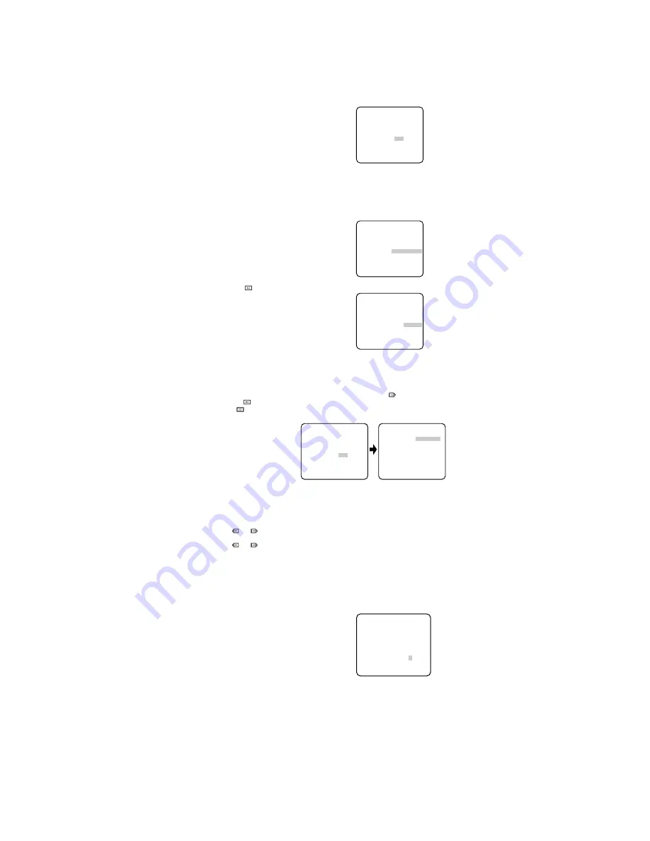
Move the cursor to the WHITE BAL
parameter and select ATW. The
white balance of the camera is
automatically set.
• Automatic White Balance Control Mode (AWC)
In this mode, accurate white balance is obtained within a colour temperature range of
approximately 2 300-10 000K.
1. Move the cursor to the WHITE BAL
parameter and select AWC
→
PUSH
SW.
2. Press
to start the white bal-
ance setup. The PUSH SW is high-
lighted to indicate that the white
balance is being set.
3. When the white balance setting is completed, the PUSH SW returns to normal dis-
play.
Note:
In case that the white balance is not set, the PUSH SW is being highlighted.
4. When you want to adjust the white balance manually, press
to select AWC and
press
. The AWC menu appears on the monitor. (When ATW is selected, press-
ing
displays the ATW menu.)
Fine Adjustment for AWC (ATW) Manually
You can add the detailed setting for white balance setting manually.
1. To set MASK SET, proceed as described in steps 2 to 4 of “ALC mode with SUPER-D2
OFF and ELC mode”.
2. Move the cursor to R.
3. Press
or
to obtain the optimum amount of red gain.
4. Move the cursor to B.
5. Press
or
to obtain the optimum amount of blue gain.
Note:
When you need to set MASK SET, re-adjust to obtain the optimum amount of red and
blue gain.
7. Audio Level Control (MIC. ON/OFF)
This item is used to adjust the audio level of the sound from microphone.
When the Microphone Selector is set to ON, this function is available.
1. Move the cursor to the AUDIO LEVEL
parameter.
2. Move the “I” cursor to adjust the audio
level.
** CAM SET UP **
CAMERA ID OFF
ALC/ELC ALC
SHUTTER OFF
AGC ON
SENS UP OFF
WHITE BAL ATW
AUDIO LEVEL ....I....
- +
END SET UP ENABLE
↵
↵
↵
** CAM SET UP **
CAMERA ID OFF
ALC/ELC ALC
SHUTTER OFF
AGC ON
SENS UP OFF
WHITE BAL AWC
→
PUSH SW
AUDIO LEVEL ....I....
- +
END SET UP ENABLE
↵
↵
** CAM SET UP **
CAMERA ID OFF
ALC/ELC ALC
SHUTTER OFF
AGC ON
SENS UP OFF
WHITE BAL AWC
→
PUSH SW
AUDIO LEVEL ....I....
- +
END SET UP ENABLE
↵
↵
** CAM SET UP **
CAMERA ID OFF
ALC/ELC ALC
SHUTTER OFF
AGC ON
SENS UP OFF
WHITE BAL AWC
AUDIO LEVEL ....I....
- +
END SET UP ENABLE
↵
↵
↵
** AWC **
R ....I....
- +
B ....I....
- +
MASK SET
RET END
↵
** CAM SET UP **
CAMERA ID OFF
ALC/ELC ALC
SHUTTER OFF
AGC ON
SENS UP OFF
WHITE BAL ATW
AUDIO LEVEL ....I....
- +
END SET UP ENABLE
↵
↵
↵