background image

2. Move the CAMERA ID to the desired

position by pressing 

/

/

/

.

3. Press 

to fix the position of the

CAMERA ID.  The mode returns to the
previous CAMERA ID menu.

Notes:

• The CAMERA ID stops at the edges of the monitor screen.
• The CAMERA ID moves faster if any of 

/

/

/

is kept pressed for a sec-

ond or more.

2. Light Control Setting (ALC/ELC)

You can select the light control mode accord-
ing to the lens type.

ALC:

If you use the auto iris lens, select this

parameter.

ELC:

If you use a fixed or manual iris lens,

select this parameter.

1. Move the cursor to the ALC/ELC parame-

ter.

2. Select ALC or ELC.

2-1. ALC Mode with SUPER-D2 ON

Super Dynamic 2 Function (SUPER-D2)

The important object in a scene is usually placed in the center of the monitor’s screen. In
SUPER-D2 mode, the dynamic range is 64 times greater than a conventional camera. This
allows you to see all the details on the monitor, even under difficult lighting condition. You
can use the SUPER-D2 function if you select ALC.

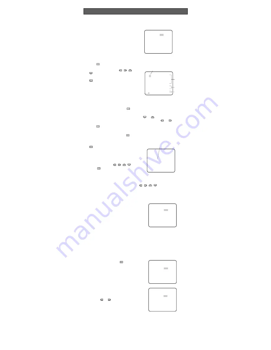
1. After selecting ALC, press 

to open

the ALC CONT menu.

2. Move the cursor to the SUPER-D2

parameter and select ON.

3. If you want to adjust the video output

level, move the cursor to the "I" posi-
tion. Adjust to the desired level by
pressing or .

SETTING PROCEDURES

   ** ALC CONT **
   BACK LIGHT COMP

SUPER-D2     OFF

MASK SET   

LEVEL        ...I.....
             -       +

 RET  END

   ** ALC CONT **
   BACK LIGHT COMP

SUPER-D2     ON

LEVEL        ...I.....
             -       +

 RET  END

1. Camera Identification (CAMERA ID) Setting

You can use the camera identification (CAMERA ID) to assign a name to the camera.  The
camera ID consists of up to 16 alphanumeric characters.  The camera ID display can be
selected on or off on the monitor screen.

To edit the CAMERA ID

1. Move the cursor to the CAMERA ID parameter.

2. Press 

.  The CAMERA ID menu appears.  The cursor on the letter “0” is highlighted.

3. Move the cursor to the character you

want to edit by pressing 

/

/

/

.

4. After selecting the character, press

.  The selected character appears

in the editing area.  (The pointer in the
editing area moves to the right auto-
matically at this moment.)

5. Repeat the steps above until all char-

acters are edited.

To enter a blank space in the CAMERA ID

Move the cursor to SPACE and press 

.

To replace a specific character in the CAMERA ID

1. Move the cursor to the editing area by pressing 

or 

.

2. Move the pointer to the character to be replaced by pressing 

or 

.  Then move

the cursor to the character area and select a new character.

3. Press 

to determine the CAMERA ID.

To erase all characters in the editing area

Move the cursor to RESET and press 

.  All characters in the editing area disappear.

To determine the display position of the CAMERA ID

1. Move the cursor to POSI, and press

.  The display shown below ap-

pears and the CAMERA ID is highlight-
ed.

WV-CP160

Highlighted

   0123456789
   ABCDEFGHIJKLM
   NOPQRSTUVWXYZ
   ().,'":;&#!?=
   +-*/%$ÄÜÖÆÑÅ

  SPACE
  POSI RET END RESET

  ................

Character Cursor

Pointer

Character
Area

Command

Editing
Area

CAMERA ID menu

    ** CAM SET UP **
CAMERA ID    OFF    
ALC/ELC      ALC    
SHUTTER      OFF
AGC          ON
SENS UP      OFF
WHITE BAL    ATW

AUDIO LEVEL  ....I....
             -       +
 
 END     SET UP ENABLE

    ** CAM SET UP **
CAMERA ID    OFF    
ALC/ELC      ALC    
SHUTTER      OFF
AGC          ON
SENS UP      OFF
WHITE BAL    ATW

AUDIO LEVEL  ....I....
             -       +
 
 END     SET UP ENABLE

Summary of Contents for WV-CP160E

Page 1: ...or at dette produkt som denne deklaration omhandler er i overensstemmelse med standarder eller andre normative dokumenter i følge bestemmelserne i direktiv 89 336 EEC Vi deklarerar härmed värt fulla ansvar för att den produkt till vilken denna deklaration hänvisar är i överensstäm melse med standarddokument eller andra normativa dokument som framställs i EEC direktiv nr 89 336 Ilmoitamme yksinomai...

Page 2: ...k a qualified service person for servicing Moisture can damage the camera and also create the danger of electric shock 4 Do not use strong or abrasive detergents when cleaning the camera body Use a dry cloth to clean the camera when dirty In case the dirt is hard to remove use a mild detergent and wipe gently PRECAUTIONS MAJOR OPERATING CONTROLS AND THEIR FUNCTIONS q Auto Iris Lens Connector This ...

Page 3: ...nput connector of the monitor 8 Rear Cover The rear cover can be removed to gain access to the terminal 6 High quality picture a 2H type vertical enhancer for greater picture sharpness b Chroma averaging circuit for better colour signal to noise ratio c Minimum of aliasing on fine objects d Expanded dynamic range by use of knee circuit e Highlight aperture correction for greater picture detail of ...

Page 4: ...e damage to the screw or deviation of focus To use the C mount lens the Lens Mount Converter C mount adapter WV AD20 should be used with the camera FOCUS OR FLANGE BACK ADJUSTMENT ALC Connector Screw Flange back Adjusting Ring Flange back Adjusting Ring Screw CONNECTIONS Caution Keep the POWER switch of the specified monitor Camera Extension Unit and Camera Drive Unit in OFF position while making ...

Page 5: ...unt the camera on the mounting bracket Make sure that the two original fixing screws are used when mounting the mount adapter as longer length screws may dam age inner components INSTALLATION OF CAMERA 3 Connect the camera and monitor with the coaxial cable and turn on the power switch of the monitor 4 While viewing the monitor picture loosen the angular control screw slight ly Adjust the camera s...

Page 6: ... about the correct settings Proceed as follows 1 Make sure that the CAM SET UP menu is not displayed a camera picture is displayed 2 While pressing both and press for a few seconds The message ALL RESET momentarily appears on the monitor This resets all adjustments and parameters to the factory default settings Editing the CAM SET UP Menu Important Notice When the SET UP DISABLE appears in the bot...

Page 7: ... assign a name to the camera The camera ID consists of up to 16 alphanumeric characters The camera ID display can be selected on or off on the monitor screen To edit the CAMERA ID 1 Move the cursor to the CAMERA ID parameter 2 Press The CAMERA ID menu appears The cursor on the letter 0 is highlighted 3 Move the cursor to the character you want to edit by pressing 4 After selecting the character pr...

Page 8: ...N or fixed level OFF Note If ON is selected for the AGC para meter the noise reduction function is automatically activated under low light conditions to reduce noise In pictures containing a moving object this may result in an afterimage 5 Electronic Sensitivity Enhancement SENS UP There are two modes for SENS UP AUTO If you select X10 AUTO for example the sensitivity is raised automatically to X1...

Page 9: ...nt to adjust the white balance manually press to select AWC and press The AWC menu appears on the monitor When ATW is selected press ing displays the ATW menu Fine Adjustment for AWC ATW Manually You can add the detailed setting for white balance setting manually 1 To set MASK SET proceed as described in steps 2 to 4 of ALC mode with SUPER D2 OFF and ELC mode 2 Move the cursor to R 3 Press or to o...

Page 10: ...or SOFT SHARP on the side of the camera 1 Move the cursor to the AP SHARP AP SOFT parameter 2 While observing the colour video monitor move the I cursor to adjust the aperture gain level 8 4 Pedestal Level Setting PEDESTAL 1 Move the cursor to the PEDESTAL parameter 2 While observing the waveform monitor or colour video monitor move the I cursor to adjust the pedestal level black level To reset to...

Page 11: ...tter Speed 1 50 OFF 1 120 1 250 1 500 1 1 000 1 2 000 1 4 000 1 10 000 s selectable Lens Mount CS mount ALC Lens DC drive Ambient Operating Temperature 10 C 50 C 14 F 122 F Ambient Operating Humidity Less than 90 Power Source From the specified monitor or camera drive unit Power Consumption 350 mA Dimensions without lens 68 W x 65 H x 126 D mm 2 11 16 W x 2 9 16 H x 4 15 16 D Weights without lens ...

Page 12: ...Matsushita Electric Industrial Co Ltd Central P O Box 288 Osaka 530 91 Japan 2000 Matsushita Communication Industrial Co Ltd All rights reserved ...

Reviews: