background image

80

Camera Title

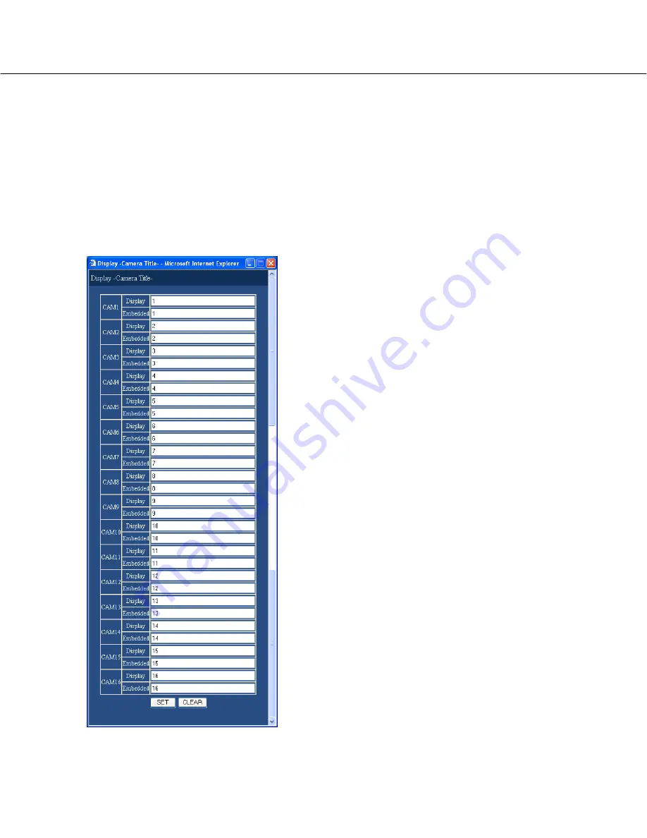
Perform the settings for the camera title.
The following window will be displayed when the
[SETUP] button is clicked. Perform the settings for each
item. 
Click the [SET] button after completing the settings, and
close the window by clicking the [¥] button at the top
right of the window.

[Display] 

Enter a camera title to be displayed on monitor 2. 
Enter up to 16 alphanumeric characters for a camera
title. 

[Embedded]

Enter a camera title to be embedded together (recorded
with images) and to be displayed when "ON" is selected
for "Embedded REC (Title)" on "Recording Setup" of
"Recording" menu and also for displaying camera titles
on monitor 1 (page 51). Enter up to 16 alphanumeric
characters for a camera title. 
The available characters for a camera title are different
depending on the selected language as follows.

<When any language except RUSSIAN is selected>
0 1 2 3 4 5 6 7 8 9 A B C D E F G H I J K L M N O P Q
R S T U V W X Y Z a b c d e f g h i j k l m n o p q r s t u
v w x y z À Ä Â Æ Ç É Ì Ñ Ò Ö Ù Ü Ø ß à á â ä å æ ç è
é ê ë ì í î ï ñ ò ó ô ö ù ú û ü ø ? " # & ( ) * + , - . / : ; SP

<When RUSSIAN is selected>

0 1 2 3 4 5 6 7 8 9 A B C D E F G H I J K L M N O P Q R S T U V W
X Y Z a b c d e f g h i j k l m n o p q r s t u v w x y z Ä Å Ç É Ñ Ö ›
Ü á à â ä ã å ç é è ê ë í ì î ï ñ ó ò ô ö õ ú ù û ü ? " #
& ( ) * + , - . / : ; SP

Time & Date Display Position 

Select a time display position from the following. 
When the settings are performed to record images with
the time display together, the time display position will
be determined on this setting. Refer to page 52 for fur-
ther information about embedding the time display. 

L - UPPER:

Displays a camera title at the upper left of

the screen.

L - LOWER:

Displays the time and date at the lower left

of the screen. 

R - UPPER:

Displays the time and date at the upper

right of the screen.

R - LOWER:

Displays the time and date at the lower

right of the screen.

Setup item

Summary of Contents for WJHD309A - DIGITAL DISK RECORDER

Page 1: ...USPEND OPERATE Digital Disk Recorder WJ HD 316A MONITOR1 MONITOR2 SHIFT DISKSELECT EL ZOOM COPY TEXT MARK PAN TILT ZOOM FOCUS IRIS LISTED BUSY A B REPEAT PAN TILT SLOW SETUP ESC SEARCH REV FWD SET GOT...

Page 2: ...2...

Page 3: ...up 19 Setup menu Quick chart 19 Basic operation with the setup menu Quick 19 Display Setup 21 REC Event Setup 24 Network Setup 28 Setup menu Advanced chart 30 Basic operation with the setup menu Advan...

Page 4: ...perating instructions There are 3 sets of operating instructions for the WJ HD316A WJ HD309A as follows Operating Instructions book Network Operating Instructions PDF Network Setup Instructions PDF th...

Page 5: ...nstalled automatically when accessing the unit using a browser If the plug in software has not been down loaded installed correctly install it from the provided CD ROM Refer to readme txt on the provi...

Page 6: ...T CASCADE OUT 16 16 3 15 15 14 14 13 2 1 13 12 12 11 11 10 10 9 9 8 8 7 7 6 6 5 5 4 4 3 3 2 2 1 1 VIDEO AUDIO IN AUDIO OUT MONITOR OUT CASCADE IN MONITOR VGA ALARM CONTROL SERIAL ALARM POWER COPY 1 MO...

Page 7: ...the network settings of this unit and the PC Performing the network settings of this unit Use the buttons on the front panel of this unit to conform the network settings to the network environment of...

Page 8: ...ed Step 4 Double click Local Area Connection 8 Screenshot 2 The control panel will be displayed Step 2 Click the Network and Internet Connections icon Screenshot 3 The Network and Internet Connections...

Page 9: ...e Local Area Connection Status window will be dis played Step 5 Click Properties Screenshot 7 The Properties window of Internet Protocol TCP IP will be displayed Step 7 Click Use the following IP addr...

Page 10: ...ns can better enhance the network security Connection example WAN Router Router Global IP Address IP Address 192 168 1 100 Subnet Mask 255 255 255 0 Default Gateway 192 168 1 1 IP Address 192 168 0 25...

Page 11: ...his unit It is impossible to access this unit from a PC without a registered IP address when ON is selected for Host Authentication on the System menu Refer to a system administrator for further infor...

Page 12: ...to a system administrator for the set user name and password Refer to page 41 for the descriptions of how to regis ter users The default user name and password are as follows User Name ADMIN Password...

Page 13: ...uch as playback status or recording sta tus will be displayed Current time recorded time displayed area When monitoring live images the current time will be displayed When playing recorded images the...

Page 14: ...Search button The SELECT SEARCH pop up window will be displayed Use this button to search the recorded images and play them Refer to the Network Operating Instructions PDF Search results will be disp...

Page 15: ...tings of the recording schedule performs recording event action by designating the time and a day of the week will be displayed Refer to page 62 for further information about this menu Switcher button...

Page 16: ...nstructions PDF for further information about filtering of the recording event list Step1 Step7 Indicates the playback speed Step1 Normal playback speed Step2 Approx 4x playback speed Step3 Approx 8x...

Page 17: ...ous recorded image and plays it REV PLAY button Reverse playback of a recorded image will be per formed PLAY button Playback of a recorded image will be performed NEXT RECORD button Skips to the next...

Page 18: ...hannels or to select the channel currently dis played in the web browser window to be selected for manual recording by performing the settings To display the Recording button and the Stop recording bu...

Page 19: ...s about the setup menu Advanced The following are available on the setup menu Quick Setup menu Quick chart Basic operation with the setup menu Quick Screenshot 1 Start operation after the top menu is...

Page 20: ...gs will be applied Important If the settings are applied all login users will be forcibly logged out The settings will not be applied by clicking the SET button in step 3 To apply the settings click t...

Page 21: ...3 YY MMM DD 03 4 1 MMM DD YY APR 1 03 DD MMM YY 1 APR 03 Time Format Select a display format for the time from the following Ex 3 o clock in the afternoon 12h 3 00 00 PM 24h 15 00 00 Time Date Adjust...

Page 22: ...ters for each camera title Embedded Enter a camera title to be embedded together recorded with images and to be displayed when ON is selected for Embedded REC Title on Recording Setup of Recording men...

Page 23: ...a channel 1 9 on a 9 split screen 9SCREEN1 9 only for the WJ HD316A Displays images from camera channels 1 9 on a 9 split screen 9SCREEN10 16 only for the WJ HD316A Displays images from camera channel...

Page 24: ...larm Screenshot 1 Start operation after the setup menu Quick is dis played by clicking the Setup tab page 20 Step 1 Click REC Event Setup Screenshot 2 The REC Event Setup menu will be displayed Step 2...

Page 25: ...ing are available for the recording rate OFF 2 ips 3 ips 5 ips 6 ips 7 5 ips 10 ips 15 ips 30 ips 60 ips 120 ips Note The camera channel number selected for REC Camera will be displayed next to the se...

Page 26: ...r event actions will not be performed ALARM Alarm Mode Performs recording writing an event log supplying the alarm output and sounding the buzzer according to the settings for Event Setup OFF Performs...

Page 27: ...clicked Perform the settings for each item Click the SET button after completing the settings and close the window by clicking the button at the top right of the window Select ON for the desired came...

Page 28: ...each item Step 3 Click the SET button after completing the settings 28 Screenshot 1 Start operation after the setup menu Quick is dis played by clicking the Setup tub page 20 Step 1 Click Network Set...

Page 29: ...d if the http port number has been changed The following port numbers are unavailable for the HTTP port number 20 21 23 25 42 67 68 69 79 105 110 123 161 162 10000 10001 10002 10003 10004 10005 10006...

Page 30: ...ording Setup Basic recording setup can be performed with this menu Emergency REC Settings for emergency recording such as the recording time and recording rate can be performed on this menu Event Even...

Page 31: ...r 2 Perform the display settings for monitor 2 such as task bar style time display position and camera title display Comm Camera Control Setting for the communication method to control cameras for eac...

Page 32: ...nce at an event occurrence Maintenance REC Rate Status Recording rate in each recording mode and image quality for each camera channel will be displayed in list form Disk Information Hard disk informa...

Page 33: ...eenshot 2 The setup menu Advanced will be displayed Step 2 Click a button on the setup menu Advanced Note When QUICK is selected for REC Type of REC Event Setup page 25 the setup menu Quick will be di...

Page 34: ...orm the settings for each item Click the SET button after completing the settings When the CLEAR button is clicked the contents of the settings will be cleared Step 5 To complete the settings click th...

Page 35: ...enu will be displayed Step 2 Perform the settings for each item Refer to page 36 for further information about the set tings for each item Step 3 Click the SET button after completing the settings Per...

Page 36: ...to operate this unit in case two or more users access this unit simulta neously A priority is followed Users with higher priority can operate this unit Pre priority The user who accessed the unit fir...

Page 37: ...pies recorded images with an alter ation detection code using the viewer software to the DVD RAM disk connected to the COPY2 port HDD Images will be copied to the copy area of the hard disk of this un...

Page 38: ...Click Time Date Setup Screenshot 2 The Time Date Setup menu will be displayed Step 2 Perform the settings for each item Refer to page 39 for further information about the set tings for each item Step...

Page 39: ...nnect ed devices and the other devices will adjust their clocks with reference to the clock of this unit Important Recording will not be performed for around 4 sec onds when changing the present time...

Page 40: ...following window will be displayed when the SETUP button is clicked Click the SET button after completing the settings and close the window by click ing the button at the top right of the window Ente...

Page 41: ...SET button after completing the settings Note Repeat steps 2 and 3 to register two or more users Screenshot 1 Start operation after the submenu of the system menu is displayed by clicking the System b...

Page 42: ...e images from camera channels 9 12 on a 4 split screen QUAD13 16 only for the WJ HD316A Displays live images from camera channels 13 16 on a 4 split screen 7SCREEN Displays images from camera channels...

Page 43: ...ll be displayed with information of the registered user Edit user information in the same way as the user registration page 41 Click the DELETE button to delete the selected user Screenshot 1 Start op...

Page 44: ...r completing the settings Note Repeat steps 2 and 3 to register two or more hosts Screenshot 1 Start operation after the submenu of the system menu is displayed by clicking the System button in the se...

Page 45: ...only for the WJ HD316A Displays live images from camera channels 9 12 on a 4 split screen QUAD13 16 only for the WJ HD316A Displays live images from camera channels 13 16 on a 4 split screen 7SCREEN...

Page 46: ...displayed with information of the registered host Corrections can be performed in the same way as registration page 44 Click the DELETE button to delete the selected host IP address Screenshot 1 Star...

Page 47: ...nified picture above Step 2 Check the desired functions that a user may operate To stop a user from operating certain functions do not check the respective function Refer to the next page for further...

Page 48: ...ed and you can refer to the access log Refer to page 14 Error Log Status The SETUP MENU is displayed and you can refer to the error log Refer to page 14 Alarm Reset An event action can be canceled Ref...

Page 49: ...to call up the saved settings Screenshot 1 Start operation after the submenu of the system menu is displayed by clicking the System button in the setup menu Advanced page 15 Step 1 Click Save Load Sa...

Page 50: ...be displayed Step 2 Perform the settings for each item Refer to page 51 for further information about the set tings for each item Step 3 Click the SET button after completing the settings Functions fo...

Page 51: ...automatically at startup Manual Recording Select a camera channel for manual recording from the following Refer to the provided operating instructions for further information about manual recording M...

Page 52: ...to the provided operating instructions for further information about each recording mode Important The priority of the event recording will be applied for the priority of pre post event recording Whe...

Page 53: ...settings 53 Screenshot 1 Start operation after the submenu of the recording menu is displayed by clicking the Recording button in the setup menu Advanced page 15 Step 1 Click Emergency REC Settings fo...

Page 54: ...ecording rate When OFF is selected for a specified camera channel images from a camera channel set to OFF will not be recorded 1 ips 2 ips 3 ips 5 ips 6 ips 7 5 ips 10 ips 15 ips 30 ips 60 ips OFF Imp...

Page 55: ...Alarm output duration can not be set for video loss Signals will be supplied continuously from the camera error output terminal pin no 17 of the ALARM CONTROL connector on the rear panel during the pe...

Page 56: ...hich the alarm signals are supplied and the alarm out put duration The following are available for alarm output duration 1 s 30 s in 1 second intervals 40 s 50 s 1 min 2 min 3 min 4 min 5 min EXT Alar...

Page 57: ...the respective SETUP button for the desired camera channel to be set Important When OFF is selected for a camera channel the motion detection function will be disabled for the camera channel Settings...

Page 58: ...selected area Step 6 Perform the settings of the detection mode method of detection in the set detection area Specifying a method of detection in a detection area is available by setting the detectio...

Page 59: ...tion is detected in area B within 10 seconds after being detected in area A Motion is detected in area C within 20 seconds after being detected in area B Motion is detected in area D within 10 seconds...

Page 60: ...spension Alarm Setup Perform the settings for the alarm displaying duration The alarm display will automatically disappear when the dis playing duration has passed Alarm Auto Reset The following will...

Page 61: ...al Setup menu will be displayed Step 2 Select polarities for each terminal by clicking the i button N O Signals will be supplied when open circuited Normally Open N C Signals will be supplied when sho...

Page 62: ...ate special days apart from the normal schedule and a recording program of another day of the week can be switched to a special day s program automatically Flowchart on how to create a schedule Follow...

Page 63: ...recording program Screenshot 3 The REC Program1 menu will be displayed Step 3 Perform the settings for each item Refer to page 64 for further information about the set tings for each item Step 4 Click...

Page 64: ...s for each camera channel must be the following values FRAME 3D ON FRAME 3D OFF 30 ips or less FIELD 60 ips or less SIF 120 ips or less Recording will be performed differently depending on the status...

Page 65: ...event recording for the camera channel that has the pre recording area in the extension unit will always be performed on the pre recording area When the recording rate is low images may be recorded f...

Page 66: ...ction video loss terminal com mand alarm Screenshot 1 Start operation after the submenu of the schedule menu is displayed by clicking the Schedule button in the setup menu Advanced page 15 Step 1 Clic...

Page 67: ...desired event to be set Screenshot 5 The setup menu for the event action will be displayed Step 5 Perform the settings for each item Refer to page 68 for further information about the set tings for e...

Page 68: ...a camera will not move to a preset position Important When OFF is selected for Auto copy of Basic Setup on System the auto copy function will not work even though ON is selected for this setting Selec...

Page 69: ...be created Screenshot 1 Start operation after the submenu of the schedule menu is displayed by clicking the Schedule button in the setup menu Advanced page 15 Step 1 Click Time Table Screenshot 2 The...

Page 70: ...perating Instructions PDF for descriptions of how to operate the viewer software ERROR REPORT MAIL Select ON or OFF to determine whether or not to send an error mail when a problem occurred Refer to p...

Page 71: ...g programs or the event programs will be applied Recording programs will be displayed with different col ors Recording program 1 event program 1 Orange Recording program 2 event program 2 Yellow Recor...

Page 72: ...ys and apply a recording schedule to the specified special days Screenshot 1 Start operation after the submenu of the schedule menu is displayed by clicking the Schedule button in the setup menu Advan...

Page 73: ...tor 1 Monitor 1 Perform the settings for the switcher function of monitor 1 Screenshot 1 Start operation after the submenu of the switcher menu is displayed by clicking the Switcher button in the setu...

Page 74: ...ect a camera position from the following 1 256 Moves to the selected preset position Does not move to any of the preset positions DWELL Select an interval time to go to the next sequential step from 1...

Page 75: ...16A Displays images from camera channels 1 13 on a 13 split screen 16SCREEN only for the WJ HD316A Displays images from camera channels 1 16 on a 16 split screen SEQ Displays images from camera channe...

Page 76: ...ep 1 Click Monitor 2 Screenshot 2 The Monitor 2 menu will be displayed Step 2 Perform the settings for the switcher function The set tings for monitor 2 are the same as the settings for mon itor 1 How...

Page 77: ...ompleting the settings Perform the settings to display on a PC monitor with the switcher function Network Perform the settings for the switcher function when displaying images on a monitor of a PC con...

Page 78: ...exactly with the set interval time for DWELL Live Sequence Setup 4 Screen Perform the settings for the sequential display when dis playing images with the sequential display on 4 split screen The fol...

Page 79: ...es or the settings of the time display position Screenshot 1 Start operation after the submenu of the display menu is displayed by clicking the Display button in the setup menu Advanced page 15 Step 1...

Page 80: ...fferent depending on the selected language as follows When any language except RUSSIAN is selected 0 1 2 3 4 5 6 7 8 9 A B C D E F G H I J K L M N O P Q R S T U V W X Y Z a b c d e f g h i j k l m n o...

Page 81: ...UPPER Displays a camera title at the upper left of the screen L LOWER Displays a camera title at the lower left of the screen R UPPER Displays a camera title at the upper right of the screen R LOWER...

Page 82: ...up menu Advanced page 15 Step 1 Click Monitor 1 Screenshot 2 The Monitor 1 menu will be displayed Step 2 Perform the display settings for monitor 1 Time Date Display Select ON or OFF to determine whet...

Page 83: ...display mode task bar style from the follow ing Refer to the provided Operating Instructions for fur ther information about the style of screen MODE1 Select MODE1 for the display mode MODE2 Select MO...

Page 84: ...ommunication settings for each camera channel to control cameras Screenshot 1 Start operation after the submenu of the communication menu is displayed by clicking the Comm button in the setup menu Adv...

Page 85: ...J HD309A OFF Dose not control camera CAM 1 16 CH are available It is possible to compensate for the video signal trans mission loss from the camera when using the VIDEO IN connector 1 8 cable compensa...

Page 86: ...menu is displayed by clicking the Comm button in the setup menu Advanced page 15 Step 1 Click PS Data Setup Screenshot 2 The PS Data Setup menu will be displayed Step 2 Perform the settings for each...

Page 87: ...ot possible 8 bit Parity Select a method of error check for a transmission at communication from the following NONE No parity check EVEN Even parity ODD Odd parity Stop Bit Select a stop bit from the...

Page 88: ...ation menu is displayed by clicking the Comm button in the setup menu Advanced page 15 Step 1 Click RS485 Setup Screenshot 2 The RS485 Setup menu will be displayed Step 2 Perform the settings for each...

Page 89: ...each camera channel Click the SET button after completing the settings and close the window by clicking the button at the top right of the window PORT1 Controls from the RS485 port 1 PORT2 Controls fr...

Page 90: ...communication menu is displayed by clicking the Comm button in the setup menu Advanced page 15 Step 1 Click RS232C Setup Screenshot 2 The RS232C Setup menu will be displayed Step 2 Perform the settin...

Page 91: ...ion speed for data transmission with a connected device from the following 9 600 19 200 38 400 bps Data Bit Select a data length for communication from the follow ing 7 8 bit Parity Select a method of...

Page 92: ...ter the submenu of the communication menu is displayed by clicking the Comm button in the setup menu Advanced page 15 Step 1 Click Network Setup 1 Screenshot 2 The Network Setup 1 menu will be display...

Page 93: ...ion by IP addresses when the unit is accessed from a PC When ON is selected only the PC with the registered IP address can access the unit and control it via a net work It is possible to enhance the n...

Page 94: ...tion after the submenu of the communication menu is displayed by clicking the Comm button in the setup menu Advanced page 15 Step 1 Click Network Setup 2 Screenshot 2 The Network Setup 2 menu will be...

Page 95: ...S Select ON or OFF to determine whether or not to use the DDNS Dynamic Domain Name Server When ON is selected perform the following settings User Name Enter a user name registered in the DDNS Enter up...

Page 96: ...NAME Enter a system name in alphanumeric characters to manage this unit by the SNMP system for example No1 Enter up to 255 alphanumeric characters LOCATION Enter a location name location where this un...

Page 97: ...will not be adjusted when event recording is being performed on any camera channel or when emergency recording is being performed Step 2 Perform the settings for the following items Time Adjustment S...

Page 98: ...ated FTP server Screenshot 1 Start operation after the submenu of the communication menu is displayed by clicking the Comm button in the setup menu Advanced page 15 Step 1 Click Network FTP Setup Scre...

Page 99: ...he settings for the rules about the file name to be sent Select whether to Use the time and date as a file name or Use a number as a file name Interval Enter a number 1 1 440 for transmission interval...

Page 100: ...Camera channel from which images were recorded by an emergency record ing Recording duration For the duration selected for Duration Post on the Network FTP Setup menu from the time when the emergency...

Page 101: ...ork Mail Setup menu will be displayed Step 2 Perform the settings for each item Refer to page 102 for further information about the set tings for each item Step 3 Click the SET button after completing...

Page 102: ...ng alarm error to be sent From address Enter the mail address of a sender Entered mail addresses will be displayed in the From sender line Enter up to 255 alphanumeric characters It is possible to ent...

Page 103: ...quality NQA NQB EXTENDED Low quality EXA EXB A is suitable for less dynamic images B is suitable for more dynamic images Settings for maintenance Maintenance Settings for the hard disk can be perform...

Page 104: ...Confirmation of the available hard disk space Disk Information Available disk space for the following disks will be displayed built in hard disk normal recording area event record ing area and copy a...

Page 105: ...tup menu Advanced page 15 Step 1 Click Version information Confirmation of version information Version Information Version information of the software and hardware will be displayed Screenshot 2 The V...

Page 106: ...Mode When changing the setting of CONTINUE to STOP during overwriting the oldest 1 hour s worth of recorded images will be deleted It is impossible to recover the deleted images even if it is set to...

Page 107: ...issued Screenshot 1 Start operation after the submenu of the maintenance menu is displayed by clicking the Maintenance button in the setup menu Advanced page 15 Step 1 Click Disk Capacity Screenshot 2...

Page 108: ...er a 4 digit number for the year when entering the time and date Manual Delete for Event Recording Area By setting the time and date images in the event recording area of the hard disk that were recor...

Page 109: ...the contents of the mail Save the edited mail contents with the file name almmail tmpl Step 2 Start up the FTP software and enter the IP address of the unit to connect to the unit Enter the user name...

Page 110: ...d Command Video loss VideoLoss Emergency recording Emergency Alarm number 05000900 1 or 2 digit 1 16 CH File name of the alarm image 05001000 xx_ALMyyyymmddhhmmss GO4 Remains blank when no alarm image...

Page 111: ...cept FULL HDD NORMAL CAPACITY REMAINS HDD EVENT CAPACITY REMAINS indicates set value 1 FULL HDD NORMAL IS FULL HDD EVENT IS FULL HDD hour meter warning HDD HOUR METER WARNING Power outage detection PO...

Page 112: ...hen an error occurred will be displayed STATUS The description of the capacity warning will be displayed except FULL HDD COPY CAPACITY REMAINS COPY1 CAPACITY REMAINS COPY2 CAPACITY REMAINS indicates s...

Page 113: ...of the 10 100BASE T port is lit Refer to a system administrator if it is not lit Reference pages Cause solution Is the Ethernet cable firmly connected to the 10 100 BASE T port Confirm the cable is f...

Page 114: ...freshed Cannot close the authenti cation window displayed when displaying the basic operation window 42 Reference pages Cause solution Symptom Audio sounds fragmentary when using the viewer soft ware...

Page 115: ...nications Security Company Unit of Matsushita Electric Corporation of America Security Systems Group www panasonic com cctv Executive Office One Panasonic Way 3E 7 Secaucus New Jersey 07094 Zone Offic...

Reviews: