background image

94

Perform the settings for the hard disk drives.
It is possible to check the histories (log) of event occur-
rence, error occurrence and access.

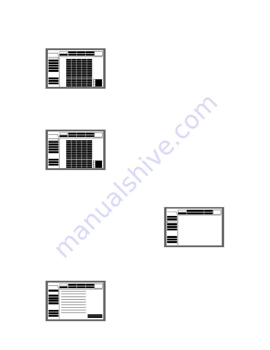
[REC Rate] Check the recording rate and
the image quality for each camera channel.

The recording rate for each recording mode for each cam-
era (as shown below) will be displayed in list form.

MANU:

Manual recording

SCHE:

Schedule recording

PRE EVT:

Pre-event recording

POST EVT:

Post-event recording

EMR:

Emergency recording

[Disk Info] Check the available hard disk
space

The available hard disk space of the following will be dis-
played: The built-in hard disk (normal recording area, event
recording area and copy area), optional extension unit
(EXT1 - 7), DVD-RAM, CD-R and DVD-R disk drive connect-
ed to the copy port (COPY1 or COPY2).
Refer to page 25 for more details on the built-in hard disk.
It is also possible to perform the settings for the hour-meter
(the active time of the HDD) warning and for the HDD safety
mode with this menu.

[Maintenance] Functions for Maintaining

REC Rate

Disk Info

Version Info

Disk End Mode

Disk Capacity

Date Delete

Event Log

Error Log

Access Log

SET UP MENU

Recording

Event

Schedule

System

Display

Comm

Switcher

LIVE

Maintenance

SUPER FINE

FINE

NORMAL

EXTENDED

AUTO

AUTO

AUTO

AUTO

AUTO

AUTO

AUTO

AUTO

AUTO

AUTO

AUTO

AUTO

AUTO

AUTO

AUTO

AUTO

1ips

1ips

1ips

1ips

1ips

1ips

1ips

1ips

1ips

1ips

1ips

1ips

1ips

1ips

1ips

1ips

1ips

1ips

1ips

1ips

1ips

1ips

1ips

1ips

1ips

1ips

1ips

1ips

1ips

1ips

1ips

1ips

1ips

1ips

1ips

1ips

1ips

1ips

1ips

1ips

1ips

1ips

1ips

1ips

1ips

1ips

1ips

1ips

1ips

1ips

1ips

1ips

1ips

1ips

1ips

1ips

1ips

1ips

1ips

1ips

1ips

1ips

1ips

1ips

CAM 1

CAM 2

CAM 3

CAM 4

CAM 5

CAM 6

CAM 7

CAM 8

CAM 9

CAM 10

CAM 11

CAM 12

CAM 13

CAM 14

CAM 15

CAM 16

MANU

SCHE

POST EVT

EMR

PRE EVT

SETUP MENU

Event

Schedule

System

Display

Comm

Switcher

LIVE

Maintenance

Recording

REC Rate

Disk Info

Version Info

Disk End Mode

Disk Capacity

Data Delete

Event Log

Error Log

Access Log

MAIN  160GB       160GB

 15000h       15000h

EXT1  160GB       160GB

 15000h       15000h

EXT2  160GB       160GB

 15000h       15000h

EXT3  160GB       160GB

15000h        15000h

EXT4  160GB       160GB

15000h        15000h

EXT5  160GB       160GB

15000h        15000h

EXT6  160GB       160GB

15000h        15000h

EXT7


Warning for Disk Life Time


HDD Safety Mode

 160GB       160GB
15000h        15000h

 160GB       160GB
 15000h       15000h
 160GB       160GB
 15000h       15000h
 160GB       160GB
 15000h       15000h
 160GB       160GB
 15000h       15000h
 160GB       160GB
 15000h       15000h
 160GB       160GB
 15000h       15000h
 160GB       160GB
 15000h       15000h

Normal REC Area 

Event REC Area 

Copy Area 

COPY 

(Rear) 

COPY 

(Front) 

3000h

OFF

Remaining

1

2

3

4

1800GB
1200GB
1000GB
1000GB
1000GB

Notes:

• The displayed available disk space on this menu

will not include the space required for data man-
agement. Therefore, the understated available disk
space will be displayed.

• When CONTINUE is selected for "Disk End Mode" of

"Maintenance", available disk space will be dis-
played as "--".

• "**" will be displayed to refer to a disk that is not

connected or a non-existent area on the disk.

8

Warning for Disk Life Time (hour meter warning
setting)

Select the duration as the maximum active time of the hard
disk from the following. A warning will be displayed when
the set time have passed. Hard disk drives will need to be
replaced after around 20 000 - 30 000 hours of operation in
case they are used at temperature of 25 °C (77 °F). (Refer to
page 5.)
10 000 h/20 000 h/30 000 h

8

HDD Safety Mode

When maintaining (HDD replacement, installation, etc.)
without turning the power of the unit off, select ON for "HDD
Safety Mode". The unit will be restarted in the HDD Safety
Mode. Refer to page 68 for further information. 
(The default setting is ON.)

[Version Info] Check the version information

Version information of the software and the hardware, and
the MAC address will be displayed.

SETUP MENU

Event

Schedule

System

Display

Comm

Switcher

LIVE

Maintenance

Recording

REC Rate

Disk Info

Version Info

Disk End Mode

Disk Capacity

Data Delete

Event Log

Error Log

Access Log


Software


Hardware (M)

(V)


Mac Address

V1.00
V1.00
V1.00
AA-BB-CC-DD-EE-FF

Summary of Contents for WJHD309 - DIGITAL DISK RECORDER

Page 1: ...s Operating Instructions TIMER ERROR ALARM RESET HDD 1 HDD 2 PULL ALARM ALARM SUSPEND OPERATE Digital Disk Recorder WJ HD 316 MONITOR1 MONITOR2 SHIFT DISKSELECT EL ZOOM COPY TEXT MARK PAN TILT ZOOM FOCUS IRIS LISTED BUSY A B REPEAT PAN TILT SLOW SETUP ESC SEARCH REV FWD SET GOTO LAST PRESET AUTO LOGOUT OSD SEQ 1 4 7 8 9 11 12 13 14 15 16 10 0 5 2 6 3 REC STOP REC STOP PAUSE PLAY ...

Page 2: ... to which this declaration relates is in conformity with the standards or other normative documents following the provisions of Directives EEC 73 23 and EEC 89 336 Nosotros declaramos bajo nuestra única responsabilidad que el producto a que hace referencia esta declaración está conforme con las normas u otros documentos normativos siguiendo las estipulaciones de las directivas CEE 73 23 y CEE 89 3...

Page 3: ...C 62 OPERATION OF THE UNIT IN THE CASCADE CONNECTION 63 Features 63 Operation using the buttons on the front panel 63 Operation using a system controller 63 INSTALLATION IN THE RACK 64 MANAGEMENT OF USERS HOSTS 65 OPERATING THE UNIT FOR THE FIRST TIME 67 Preparation for maintenance HDD replacement installation etc 68 CONNECTIONS 70 Connections when the unit is used independently 70 Connections wit...

Page 4: ...ode quality and recording rate can be changed to high quality to record pictures Motion Detection Function VMD It is possible to start recording automatically when motion is detected in a shooting area Frame Switcher Function It is possible to display pictures of four or more cam eras on a single monitor multi screen splitting the monitor screen into 4 7 9 10 13 or 16 sections using the WJ HD316 a...

Page 5: ...as to the indications of equipment classi fication and power source etc Built in hard disk drives Hard disk drives are vulnerable to vibration Handle them with care It is possible to damage them if they are moved while their motors are still running Do not move them just after turning their power on or off for around 30 sec onds Hard disk drives are perishable They will need to be replaced after a...

Page 6: ...descriptions of how to perform the required settings and how to connect to other devices Adobe Reader is required to read these operating instruc tions PDF on the provided CD ROM When the Adobe Reader is not installed on the PC download the latest Adobe Reader from the Adobe web site and install it WJ HD300 or HD300 shown in the illustrations used in these operating instructions indicate this unit...

Page 7: ...cator off press the ALARM RESET but ton r Alarm Reset Button ALARM RESET Pressing this button cancels alarm activation and returns the system to the condition before the alarm was activated t Error indicator ERROR Blinks orange when an error occurs that will not keep the unit from running Blinks red when an error occurs that may cause the system to go down Refer to page 56 for further information ...

Page 8: ...search menu 3 Set Button SET Works differently depending on the situations listed below Plays recorded images at the current playback speed when this button is pressed during fast playback Registers preset positions of cameras Activates the auto focus function Sets the alarm suspension mode on off Determines the setting of parameters on the setup menus 4 Jog Dial Works differently depending on the...

Page 9: ...ARM POWER COPY 1 MODE EXT STORAGE 10 100BASE T RS485 CAMERA DATA AC IN SIGNAL GND 1 4 2 1 2 IN OUT CASCADE OUT 16 16 3 15 15 14 14 13 2 1 13 12 12 11 11 10 10 9 9 8 8 7 7 6 6 5 5 4 4 3 3 2 2 1 1 VIDEO AUDIO IN AUDIO OUT MONITOR OUT CASCADE IN MONITOR VGA ALARM CONTOROL SERIAL ALARM POWER COPY 1 MODE EXT STORAGE 10 100BASE T RS485 CAMERA DATA AC IN SIGNAL GND 1 4 2 w t y ui o 0 1 3 5 8 2 4 6 7 e r ...

Page 10: ...on and off 8 Signal Ground Terminal SIGNAL GND 9 Power Cord Inlet AC IN Connect the power cord to this inlet On Monitor 1 To display only live image The negative circled numbers indicate the default positions of camera title q time w and event display e Important The SETUP MENU will be displayed on monitor 2 and the VGA monitor It is impossible to display the SETUP MENU on monitor 1 It will take a...

Page 11: ...a title in list form Not display the camera title Important Since the VGA output from this unit is the same as for televisions 720 H x 576 V pixels vertical frequency of 50 Hz it may be possible that both the left and right edges can not fit onto the screen depending on the VGA monitor It is impossible to use the MONITOR VGA connector when connecting the unit in the cascade connection It may take ...

Page 12: ...ar will be dis played Mode 2 Displays the status on the main bar the left bar and the right bar Mode 3 Displays the status only on the main bar and does not display information on the left bar and the right bar Note Mode 2 and Mode 3 are graphic operated They may not be as clear as Mode 1 ...

Page 13: ...lay Area Live Playback Indicates the live image display status Indicates that playback is currently being performed with the displayed playback speed Live image is displayed Live images are displayed sequentially 5 Currently playing 4 Currently playing in reverse h Currently pausing 2 Currently playing at fast speed 1 Currently playing in reverse at fast speed Indicates that recording is currently...

Page 14: ...tes partition nn Available disk size n Number of connector that an external recording device is connected to Abbreviation of partition Status Displayed abbreviation Normal recording area NML Event recording area EVT Copy area CPY External recording device connected to the COPY1 port on the rear panel CP1 External recording device connected to the COPY2 port on the front panel CP2 Note Refer to pag...

Page 15: ...ormation NML Available disk space of the normal record ing area used for manual recording and schedule recording EVT Available disk space of the event recording area used for event recording and emergency recording Indicated Item Camera Indicates recording and displaying status Grey Camera currently not displayed or not con nected to the respective channel Green Camera displayed on the monitor Ora...

Page 16: ...ompleted Important When using the optional extension unit WJ HDE300 series turn on the power of this unit after turning on the power of all extension units c Enter a user name and password Rotate the jog dial to select a character to be entered in the cursor position It is also possible to enter numbers by pressing the camera selection buttons 1 10 0 for the WJ HD316 1 9 0 for the WJ HD309 To move...

Page 17: ...ips 1ips 1ips 1ips 1ips 1ips 1ips 1ips 1ips 1ips 1ips 1ips 1ips 1ips 1ips 1ips 1ips 1ips 1ips 1ips 1ips 1ips 1ips 1ips 1ips 1ips 1ips 1ips 1ips 1ips 1ips 1ips CAM 1 CAM 2 CAM 3 CAM 4 CAM 5 CAM 6 CAM 7 CAM 8 CAM 9 CAM 10 CAM 11 CAM 12 CAM 13 CAM 14 CAM 15 CAM 16 MANU SCHE POST EVT EMR PRE EVT Schedule System Comm Switcher SETUP MENU LIVE Maintenance Recording Event Display Basic Setup Time Date Use...

Page 18: ...OP button Playback will stop and the indicator on the PLAY PAUSE button will go off Turn off the power of the unit after confirming that the HDD1 and HDD2 indicators are off Important Detach the plug from the outlet if not operating the unit for a length of time When the unit has not been used for a certain period turn on the power of the unit approximately once a week and perform recording playba...

Page 19: ...be recorded with the default setting It is possible to record only images displayed on monitor 2 and the VGA monitor by changing the settings R 2 R 1 LOGOUT MONITOR1 MONITOR2 5 9 2 6 10 0 14 13 3 7 11 SHIFT SEQ COPY DISKSELECT EL ZOOM TEXT LOGOUT 4 8 12 OSD MARK 1 15 16 BUSY 316 REV FWD STOP PLAY PAUSE REC REC STOP SEARCH SETUP ESC PAN TILT SLOW A B REPEAT GOTO LAST LISTED ZOOM FOCUS IRIS PRESET A...

Page 20: ... 2 5 700 500 1 000 700 1 500 1 000 2 000 1 500 4 2 400 300 600 400 900 600 1 200 900 5 300 200 500 300 700 500 1 000 700 6 3 300 200 400 300 600 400 800 600 8 3 200 100 300 200 400 300 600 400 12 5 100 100 200 100 300 200 400 300 25 70 50 100 70 100 100 200 100 50 30 20 50 30 70 50 100 70 Important The possible recording durations on the above tables are the average durations under the conditions ...

Page 21: ...is played on the monitor to indicate which camera is being recorded When starting emergency recording while another recording with a different recording mode except event recording is being performed the indicator on the REC button will remain lit and the other recording will resume after the emergency recording has finished Recording duration of emergency recording Recording duration of emergency...

Page 22: ...layback Press the STOP button The indicator on the PLAY PAUSE button will go off and playback will be stopped Live images will be displayed on monitor 2 and the VGA monitor PLAYBACK R 2 R MONITOR1 MONITOR2 1 5 9 13 2 6 10 0 14 3 7 11 15 4 8 12 16 SEQ SHIFT OSD STOP PLAY PAUSE REC REC STOP ZOOM FOCUS TEXT COPY DISKSELECT EL ZOOM MARK LOGOUT IRIS PRESET AUTO A B REPEAT GOTO LAST LISTED SEARCH BUSY S...

Page 23: ... to the start time of the previous one Rotating the jog dial coun terclockwise at the point around the start time of the recording will skip to the start time of two more previous recordings If there is no next or previous recorded image current playback will continue Play the latest recorded image Press the GO TO LAST button to play the latest recorded image Multi screen display It is possible to...

Page 24: ...It is possible to play recorded images between two designated points repeatedly q Designate a start point A by pressing the A B REPEAT button during playback The A B REPEAT indicator will light and the time of point A will be displayed To cancel the designated point press the SETUP ESC button w Designate an end point B by pressing the A B REPEAT button during playback When the start point and the ...

Page 25: ...size of each recording area differs depend ing on the settings Refer to a system administrator for further information z Press the SHIFT button The SHIFT indicator will light x Press the camera selection button 9 7 for the WJ HD309 DISK SELECT The DISK SELECT window will be displayed on monitor 2 and the VGA monitor PLAYBACK IMAGE ON A DESIGNATED DISK Copy area Built in hard disk Normal recording ...

Page 26: ...indicator on the PLAY PAUSE button will go off and playback will stop Live images will be displayed on monitor 2 and the VGA monitor Note Pressing the PLAY PAUSE button after stopping play back will start playback from the end point of the recorded image played last time R 2 R 1 LOGOUT MONITOR1 MONITOR2 5 9 2 6 10 0 14 13 3 7 11 SHIFT SEQ COPY DISKSELECT EL ZOOM TEXT LOGOUT 4 8 12 OSD MARK 1 15 16...

Page 27: ... time When there are images recorded after the entered time the oldest recorded image after the entered time will be played When there are no images recorded after the entered time the newest recorded image before the entered time will be played v Press the STOP button The indicator on the PLAY PAUSE button will go off and stop playback Live images will be displayed on monitor 2 and the VGA monito...

Page 28: ...ording Refer to page 21 VMD Event recording performed when motion was detected Refer to page 32 TERMINAL Event recording performed when a terminal alarm was detected COMMAND Event recording performed when a command alarm was detected VIDEO LOSS Event recording performed when video loss occurred MANUAL Manual recording Refer to page 19 SCHEDULE Schedule recording Refer to page 105 TEXT Search for o...

Page 29: ...ed Number of the listed data The number of the listed data will be displayed Search information The search filter will be displayed A filter of the currently displayed list will be dis played in orange Recording Event Thumbnail Window Time and date Camera channel Recording event Number of listed data Time and date When searched by recording event The time when recording started will be displayed W...

Page 30: ...1ch 01ch 01ch 01ch MANUAL MANUAL MANUAL MANUAL MANUAL MANUAL MANUAL MANUAL CAM REC EVT ABCDEFGHIJ ABCDEFGHIJ ABCDEFGHIJ ABCDEFGHIJ ABCDEFGHIJ ABCDEFGHIJ ABCDEFGHIJ ABCDEFGHIJ TEXT 25 APR 03 12 34 56 AM 25 APR 03 12 34 56 AM 25 APR 03 12 34 56 AM 25 APR 03 12 34 56 AM 25 APR 03 12 34 56 AM 25 APR 03 12 34 56 AM 25 APR 03 12 34 56 AM 25 APR 03 12 34 56 AM TIME DATE SEARCH REC EVENT SEARCH VMD SEARCH...

Page 31: ...and rotate the jog dial to ON Press the SET button to determine the selection The recording events of the selected filter will be listed Filter recording events by text information Rotate the jog dial to select OFF WITH TEXT or WITHOUT TEXT Press the SET button to determine the selection The recording events filtered by the selected filter will be listed v Rotate the jog dial to select the recordi...

Page 32: ...ious search Use the arrows button C D to switch between displaying the list window and the thumbnail window alternately List window TIME DATE 01ch 01ch 01ch 01ch 01ch 01ch 01ch 01ch CAM 25 APR 03 12 34 56 AM 25 APR 03 12 34 56 AM 25 APR 03 12 34 56 AM 25 APR 03 12 34 56 AM 25 APR 03 12 34 56 AM 25 APR 03 12 34 56 AM 25 APR 03 12 34 56 AM 25 APR 03 12 34 56 AM TIME DATE SEARCH REC EVENT SEARCH VMD ...

Page 33: ... time range set in step 3 the motion detection area setup window will not be displayed when the SET button is pressed b Rotate the jog dial to select SETUP AREA on the status bar Note It is possible to set all displayed areas as motion detection areas by pressing the SET button after select ing ALL AREAS n Move the cross cursor using the arrows button to a point to be determined as the start point...

Page 34: ...detection area It is possible to set up to 4 motion detection areas by repeating steps 6 and 7 Rotate the jog dial to select SENSITIVITY on the status bar Note Depending on the position of the set detection areas the sensitivity indications of the detection areas may be displayed overlapping each other Move the cross cursor to the motion detection area to apply the sensitivity using the arrows but...

Page 35: ...n to start play back The LISTED indicator and the indicator on the PLAY PAUSE button will light and playback of the selected recording will start Note It is possible to skip from the playback point to the listed time motion detected time by rotating the jog dial when the LISTED indicator is lit To return to normal playback press the LISTED button 6 Press the STOP button to stop playback The indica...

Page 36: ... C and 30 sec for area D An event action will be performed when an object keeps moving longer than the set period in the specified detection area Important When images to be searched are recorded with a low recording rate the DURATION mode may not work cor rectly It may take some time to search according to the con tents of the recorded images To delete the motion detection area z Rotate the jog d...

Page 37: ...s the STOP button The indicator on the PLAY PAUSE button will go off and playback will be stopped Live images will be displayed on monitor 2 and the VGA monitor R 2 R 1 LOGOUT MONITOR1 MONITOR2 5 9 2 6 10 0 14 13 3 7 11 SHIFT SEQ COPY DISKSELECT EL ZOOM TEXT LOGOUT 4 8 12 OSD MARK 1 15 16 BUSY 316 REV FWD STOP PLAY PAUSE REC REC STOP SEARCH SETUP ESC PAN TILT SLOW A B REPEAT GOTO LAST LISTED ZOOM ...

Page 38: ...ill be displayed with x2 zoomed size Zooming level will change each time the EL ZOOM button is pressed x2 x4 OFF Notes When an image is zoomed in on x2 or x4 it is possible to move the zoomed image using the arrows button When any indicator of PAN TILT ZOOM FOCUS IRIS PRESET AUTO is lit it is impossible to use the EL ZOOM function R 2 R MONITOR1 MONITOR2 1 5 9 13 2 6 10 0 14 3 7 11 15 4 8 12 16 SE...

Page 39: ... on the selected multi screen on the VGA mon itor To display on a single screen Press the SHIFT button The SHIFT indicator will go off Press any of the camera selection buttons Live images will be displayed on a single screen When displaying on a 4 split screen Each time the camera selection button 4 is pressed the displayed camera channels will be changed as follows WJ HD316 1 4 CH 5 8 CH 9 12 CH...

Page 40: ...ton When trying to display on a single screen or multi screen during the sequential display the sequential display will be stopped When monitor 2 is selected in step 1 the sequential display will also start on the VGA monitor R 2 R MONITOR1 MONITOR2 1 5 9 13 2 6 10 0 14 3 7 11 15 4 8 12 16 SEQ SHIFT OSD STOP PLAY PAUSE REC REC STOP ZOOM FOCUS TEXT COPY DISKSELECT EL ZOOM MARK LOGOUT IRIS PRESET AU...

Page 41: ...m Zooms in out on images Depending on models of the con nected cameras the image size for the respective zooming level may be different For further information refer to the operating instruction for the camera z Press the ZOOM FOCUS button The ZOOM FOCUS indicator will light x Use the arrows button CD to zoom in on or out of the displayed image Press the arrows button downward C to zoom out and up...

Page 42: ...itions and move a camera to a preset position by performing the following steps In this case perform the settings using the setup menu of camera Register Preset Positions of Cameras Up to 64 preset positions can be registered z Press the PAN TILT button and move the cam era to a desired position to be registered as a preset position x Press the SET button The REGISTRATION PRESET POSITION window wi...

Page 43: ...ered as a preset position with the selected preset position number To cancel the selected preset position select CANCEL using the arrows button and press the SET button The set ting will be canceled and the REGISTRATION PRESET POSITION window will be closed R 2 R MONITOR1 MONITOR2 1 5 9 13 2 6 10 0 14 3 7 11 15 4 8 12 16 SEQ SHIFT OSD STOP PLAY PAUSE REC REC STOP ZOOM FOCUS TEXT COPY DISKSELECT EL...

Page 44: ...he radio button next to AUTO PAN using the jog dial c Select OK using the arrows button and press the SET button The PRESET AUTO PAN window will be closed and auto function will start During auto function it is impossible to register a preset position To close the PRESET AUTO PAN window select CANCEL using the arrows button and press the SET but ton The setting will be canceled and the PRESET AUTO...

Page 45: ...nce The event action will be performed according to the set tings when an event occurs There are 2 event action modes for the alarm mode ALARM and the activity detection mode ACT DET for each event type The event action will be different accord ing to the event action mode set When an event of the alarm mode ALARM occurs this unit activates the alarm action About the event action mode Alarm Mode A...

Page 46: ...ce Alarm Output Sends a signal to the device connected to the ALARM CONTROL connector and the connected device such as a buzzer will be activated Starts recording automatically Starts recording the image from the location of the event occurrence automatically Moves a camera to the preset position A camera will move to the preset position registered in advance Announces an event occurrence by sendi...

Page 47: ...ctivate temporarily the alarm actions z Press both the ALARM RESET button and the SET button at the same time The ALARM SUSPEND indicator will light To stop suspending the alarm actions x Press both the ALARM RESET button and the SET button at the same time again The ALARM SUSPEND indicator will go off Note When an external switch is connected to the ALARM CONTROL connector on the rear panel it is...

Page 48: ... indicator will light To copy recorded images during playback pause the play back temporarily x Press the COPY button The DATA COPY window will be displayed on monitor 2 and the VGA monitor The DATA COPY window will not be displayed when a thumbnail window is displayed In this case display a list window using the arrows button C D Notes When the auto copy function is enabled the DATA COPY window w...

Page 49: ...e disk of COPY1 Confirm the SHIFT indicator is lit Then press the COPY button and 1 simultaneously for 2 seconds or more To eject the disk of COPY2 Confirm the SHIFT indicator is lit Then press the COPY button and 2 simultaneously for 2 seconds or more Copying will be performed in the following order Viewer Software Images Audio Depending on the set time range for PERIOD some of images and audio m...

Page 50: ... AUTO AUTO AUTO AUTO AUTO AUTO AUTO AUTO AUTO AUTO AUTO AUTO AUTO 1ips 1ips 1ips 1ips 1ips 1ips 1ips 1ips 1ips 1ips 1ips 1ips 1ips 1ips 1ips 1ips 1ips 1ips 1ips 1ips 1ips 1ips 1ips 1ips 1ips 1ips 1ips 1ips 1ips 1ips 1ips 1ips 1ips 1ips 1ips 1ips 1ips 1ips 1ips 1ips 1ips 1ips 1ips 1ips 1ips 1ips 1ips 1ips 1ips 1ips 1ips 1ips 1ips 1ips 1ips 1ips 1ips 1ips 1ips 1ips 1ips 1ips 1ips 1ips CAM 1 CAM 2 CA...

Page 51: ...nt Log Error Log Access Log Auto Delete Manual Delete for Normal Recording Area Delete before 01 JAN 03 Manual Delete for Event Recording Area Delete before 01 JAN 03 Disc Format of DVD COPY1 COPY2 DELETE FORMAT FORMAT OFF DELETE Event Schedule System Display Comm Switcher SETUP MENU LIVE Maintenance Recording REC Rate Disk Info Version Info Disk End Mode Disk Capacity Data Delete Event Log Error ...

Page 52: ...11 CAM 12 CAM 13 CAM 14 CAM 15 CAM 16 MANU SCHE POST EVT EMR PRE EVT REC Rate Disk Info Version Info Disk End Mode Disk Capacity Date Delete Event Log Error Log Access Log SET UP MENU Recording Event Schedule System Display Comm Switcher LIVE Maintenance SUPER FINE FINE NORMAL EXTENDED AUTO AUTO AUTO AUTO AUTO AUTO AUTO AUTO AUTO AUTO AUTO AUTO AUTO AUTO AUTO AUTO 1ips 1ips 1ips 1ips 1ips 1ips 1ip...

Page 53: ...w will be closed automatically after com pleting formatting Press the SETUP ESC button to close the SETUP MENU window Live images will be displayed on monitor 2 and the VGA monitor OK CANCEL All of data in the COPY1 is going to be erased R 2 R 1 LOGOUT MONITOR1 MONITOR2 5 9 2 6 10 0 14 13 3 7 11 SHIFT SEQ COPY DISKSELECT EL ZOOM TEXT LOGOUT 4 8 12 OSD MARK 1 15 16 BUSY 316 REV FWD STOP PLAY PAUSE ...

Page 54: ...e TEXT button again to edit text infor mation R 2 R MONITOR1 MONITOR2 1 5 9 13 2 6 10 0 14 3 7 11 15 4 8 12 16 SEQ SHIFT OSD STOP PLAY PAUSE REC REC STOP ZOOM FOCUS TEXT COPY DISKSELECT EL ZOOM MARK LOGOUT IRIS PRESET AUTO A B REPEAT GOTO LAST LISTED SEARCH BUSY SETUP ESC SET REV FWD PAN TILT SLOW WJ HD316 LOGOUT R 2 R MONITOR1 MONITOR2 1 4 7 2 5 8 0 3 6 9 TEXT SEQ SHIFT OSD ZOOM FOCUS COPY DISKSE...

Page 55: ...ext n Press the SET button to apply the edited char acters To cancel the edit press the SETUP ESC button The edit ed characters will not be applied Important It is impossible to edit text information using the system controller TEXT INFORMATION EDIT TEXT SET SET CANCEL ESC Digital Disc Recorder WJ HD316 R 2 R MONITOR1 MONITOR2 1 5 9 13 2 6 10 0 14 3 7 11 15 4 8 12 16 SEQ SHIFT OSD STOP PLAY PAUSE ...

Page 56: ...e the ERROR indi cator is lit Error reset Status Description Solution Error Error Warning Recorded image has been altered Playback will be paused Failed to write data on the HDD The hard disk may be malfunctioning and may not work correctly Press the ALARM RESET button to can cel the error status The unit will be in the error half reset error reset condition Press the PLAY PAUSE button to resume p...

Page 57: ...fferent format disk has been inserted etc An error has occurred on the hard disk and the hard disk has been unmounted from the system automatically Status Description Solution Camera number Partition number Refer to page 14 nn Available disk space percentage n COPY port number to which an external recording device is connected Note The available disk space warning will be given only once when the ...

Page 58: ...e thumbnail window alternately Display a list thumbnail Move the cursor to select SEARCH SET SEARCH SEARCH SEARCH STILL EL ZOOM CAM SET CAM SET SET MON ESC SETUP ESC Set on the SETUP MENU Set on the SETUP MENU Set on the SETUP MENU Set on the SETUP MENU Press A or B Press C or D UP DOWN R UP DOWN L R DOWN L R UP L R SETUP FUNCTION SETUP FUNCTION SETUP FUNCTION SETUP FUNCTION SETUP FUNCTION SETUP F...

Page 59: ...TOP Alarm reset Alarm suspension Manual recording Stop manual recording Stop playback manual recording Play Stop playback Play at normal speed Play at 2x speed Play at 5x speed Play at 10x speed Play at 20x speed Play at 50x speed Play at 100x speed Reverse play at normal speed Reverse play at 2x speed Reverse play at 5x speed Reverse play at 10x speed Reverse play at 20x speed Reverse play at 50x...

Page 60: ... HD309 Select the normal recording area event recording area of the HDD For the WJ HD316 Select the normal recording area event recording area of the HDD For the WJ HD309 Select monitor 1 Select monitor 2 SETUP FUNCTION SETUP FUNCTION SETUP FUNCTION SETUP FUNCTION SETUP FUNCTION SETUP FUNCTION SETUP FUNCTION SETUP FUNCTION SETUP FUNCTION SETUP FUNCTION SETUP FUNCTION REV FWD Rotate the jog daial R...

Page 61: ...isplay the DATA COPY menu For the WJ HD316 Display the DATA COPY menu For the WJ HD309 Available only when displaying live images or a list or when pausing playback Available only when displaying live images or a list or when pausing playback Cancel copying For the WJ HD316 Cancel copying For the WJ HD309 Switch displayed informa tion For the WJ HD316 Switch displayed informa tion For the WJ HD309...

Page 62: ...also possible to send an e mail with a recorded image of the place where the event occurred Host authentication It is possible to restrict devices from operating this unit if their IP addresses are not registered System Requirements of a PC It is recommended to operate this unit using a PC that meets the following system requirements If using a PC that does not meet the following system requiremen...

Page 63: ...of the system controller or page 58 for descriptions of how to oper ate a PS Data compatible system controller System Controller PS Data compatible system controller Monitor 2 ALARM TIMER HDD 2 ERROR HDD 1 ALARM SUSPEND ALARM RESET OPERATE MONITOR1 MONITOR2 1 5 9 13 2 6 10 0 14 3 7 11 15 4 8 12 16 SEQ SHIFT OSD PAN TILT STOP PLAY PAUSE REC REC STOP ZOOM FOCUS TEXT COPY DISKSELECT EL ZOOM MARK LOGO...

Page 64: ...kets accessories Rack mounting brackets accessories Rack mounting screws For our rack Nominal diameter 5 tapping accessory Important The cooling fan inside the unit is perishable and must be replaced periodically Do not block the ventilation openings or slots in the cover to prevent the unit from overheating If the rack is subject to vibration secure the rear of the unit to the rack using addition...

Page 65: ...ready logged in this user can log in and the other user who has already logged in will be forced to log out When a user s priority is lower than the one of the other user who has already logged in this user cannot log in When another user has already logged in any user except administrators cannot log in regardless of priority When an administrator has logged in the other user who has already logg...

Page 66: ...ority Pre priority Post priority When a host s priority is higher than the one of the other host who has already logged in this host can log in and the other host who has already logged in will be forced to log out When a host s priority is lower than the one of the other host who has already logged in this host cannot log in Any host cannot log in regardless of priority However it is possible to ...

Page 67: ...ETUP MENU will be displayed Adjust the clock of the unit with this menu Refer to page 17 for further information about clock adjust ment b With the default setting the unit is ready to start manual recording Perform the settings for recordings or event actions according to your needs Digital Disk Recorder WJ HD300 HDD DISK MENU TOP MENU FORMAT MIRROR ON REMOVE RESTART EXIT MIRROR OFF Information o...

Page 68: ...CAM 13 CAM 14 CAM 15 CAM 16 MANU SCHE POST EVT EMR PRE EVT REC Rate Disk Info Version Info Disk End Mode Disk Capacity Date Delete Event Log Error Log Access Log SET UP MENU Recording Event Schedule System Display Comm Switcher LIVE Maintenance SUPER FINE FINE NORMAL EXTENDED AUTO AUTO AUTO AUTO AUTO AUTO AUTO AUTO AUTO AUTO AUTO AUTO AUTO AUTO AUTO AUTO 1ips 1ips 1ips 1ips 1ips 1ips 1ips 1ips 1ip...

Page 69: ...ET button The REMOVE indication will change to REMOVING The power supply to the front panel will be cut and the unit will be unable to operate with the front panel Detach the cable from the front panel and start replacing the built in hard disk Start from step 2 on page 128 to replace the built in hard disk The REMOVING indication will return to REMOVE by attaching the cable to the front panel The...

Page 70: ...onnections Notes The SETUP MENU will be displayed on monitor 2 and the VGA monitor It is impossible to display the SETUP MENU on monitor 1 The same images displayed on monitor 2 will be displayed on the VGA monitor Depending on the connected monitor flickering may occur when displaying the SETUP MENU In this case it is rec ommended to use the VGA monitor or a dirtectly connected PC using a LAN cab...

Page 71: ...table system 1 2 IN OUT CASCADE OUT 16 16 3 15 15 14 14 13 2 1 13 12 12 11 11 10 10 9 9 8 8 7 7 6 6 5 5 4 4 3 3 2 2 1 1 VIDEO AUDIO IN AUDIO OUT MONITOR OUT CASCADE IN MONITOR VGA ALARM CONTOROL SERIAL ALARM POWER COPY 1 MODE EXT STORAGE 10 100BASE T RS485 CAMERA DATA AC IN SIGNAL GND 1 4 2 This unit Cable attached to the extension unit Extension unit WJ HDE300 series POWER AC IN SIGNAL GND 1 2 IN...

Page 72: ...14 13 3 7 11 SHIFT SEQ COPY DISKSELECT EL ZOOM TEXT LOGOUT 4 8 12 OSD MARK 1 15 16 BUSY REV FWD STOP PLAY PAUSE REC REC STOP SEARCH SETUP ESC PAN TILT SLOW A B REPEAT GOTO LAST LISTED ZOOM FOCUS IRIS PRESET AUTO SET ALARM RESET S VIDEO COPY 2 VIDEO OUT AUDIO OUT 1 2 IN OUT CASCADE OUT 16 16 3 15 15 14 14 13 2 1 13 12 12 11 11 10 10 9 9 8 8 7 7 6 6 5 5 4 4 3 3 2 2 1 1 VIDEO AUDIO IN AUDIO OUT MONIT...

Page 73: ...AUDIO OUT connector on the rear panel of this unit will be supplied to the AUDIO OUT connector inside the connectors cover on the front panel VTR Open the connectors cover ALARM TIMER HDD 2 ERROR HDD 1 ALARM SUSPEND OPERATE LOGOUT MONITOR1 MONITOR2 5 9 2 6 10 0 14 13 3 7 11 SHIFT SEQ COPY DISKSELECT EL ZOOM TEXT LOGOUT 4 8 12 OSD MARK 1 15 16 BUSY REV FWD STOP PLAY PAUSE REC REC STOP SEARCH SETUP ...

Page 74: ...a compatible device it is necessary to set each item of PS Data Setup of Comm on the SETUP MENU according to the system configuration The PS Data is our exclusive protocol Contact the dealer about devices that can be connected When connecting this unit with a controller System Controller Controller Termination ON Unit Address 1 RS485 cable provided with the controller Mode switch No 7 ON No 8 OFF ...

Page 75: ...N PS Data setup of Comm on the SETUP MENU Unit Address System 1 Unit Address Controller 2 No 7 OFF No 8 ON POWER ON OFF ALARM Data Multiplex Unit WJ MP204 ALARM SUSPEND 1 2 3 4 ESC SET RESET SUSPEND SET UP ALARM UNIT 0 9 8 7 6 5 4 3 2 1 POWER ON OFF ALARM Data Multiplex Unit WJ MP204 ALARM SUSPEND 1 2 3 4 ESC SET RESET SUSPEND SET UP ALARM UNIT 0 9 8 7 6 5 4 3 2 1 RS485 cable RS485 cable Mode swit...

Page 76: ... 13 2 1 13 12 12 11 11 10 10 9 9 8 8 7 7 6 6 5 5 4 4 3 3 2 2 1 1 VIDEO AUDIO IN AUDIO OUT MONITOR OUT CASCADE IN MONITOR VGA ALARM CONTOROL SERIAL ALARM POWER COPY 1 MODE EXT STORAGE 10 100BASE T RS485 CAMERA DATA AC IN SIGNAL GND 1 4 2 1 2 IN OUT CASCADE OUT 16 16 3 15 15 14 14 13 2 1 13 12 12 11 11 10 10 9 9 8 8 7 7 6 6 5 5 4 4 3 3 2 2 1 1 VIDEO AUDIO IN AUDIO OUT MONITOR OUT CASCADE IN MONITOR ...

Page 77: ... 1 4 2 1 2 IN OUT CASCADE OUT 16 16 3 15 15 14 14 13 2 1 13 12 12 11 11 10 10 9 9 8 8 7 7 6 6 5 5 4 4 3 3 2 2 1 1 VIDEO AUDIO IN AUDIO OUT MONITOR OUT CASCADE IN MONITOR VGA ALARM CONTOROL SERIAL ALARM POWER COPY 1 MODE EXT STORAGE 10 100BASE T RS485 CAMERA DATA AC IN SIGNAL GND 1 4 2 No 7 ON No 8 OFF No 7 OFF No 8 OFF System Controller First unit this unit System 1 Controller 2 Second unit System...

Page 78: ... 13 2 1 13 12 12 11 11 10 10 9 9 8 8 7 7 6 6 5 5 4 4 3 3 2 2 1 1 VIDEO AUDIO IN AUDIO OUT MONITOR OUT CASCADE IN MONITOR VGA ALARM CONTOROL SERIAL ALARM POWER COPY 1 MODE EXT STORAGE 10 100BASE T RS485 CAMERA DATA AC IN SIGNAL GND 1 4 2 No 7 OFF No 8 OFF No 7 OFF No 8 OFF First unit this unit System 1 Controller 1 Second unit System 2 Controller 2 Third unit System 3 Controller 3 Monitor 2 Mode sw...

Page 79: ... 3 2 2 1 1 VIDEO AUDIO IN AUDIO OUT MONITOR OUT CASCADE IN MONITOR VGA ALARM CONTOROL SERIAL ALARM POWER COPY 1 MODE EXT STORAGE 10 100BASE T RS485 CAMERA DATA AC IN SIGNAL GND 1 4 2 No 7 OFF No 8 OFF No 7 OFF No 8 OFF POWER ON OFF ALARM Data Multiplex Unit WJ MP204 ALARM SUSPEND 1 2 3 4 ESC SET RESET SUSPEND SET UP ALARM UNIT 0 9 8 7 6 5 4 3 2 1 First unit this unit System 1 Controller 2 Second u...

Page 80: ...total length of the RS485 cable from this unit is 1 200 meters at the maximum 1 1 connection Connect a camera to the RS485 CAMERA port Example When the RS485 cameras are connected to the CAMERA IN connectors 9 and 13 IN OUT CASCADE OUT 16 16 4 15 15 14 14 13 2 1 13 12 12 11 11 10 10 9 9 8 8 7 7 6 6 5 5 4 4 3 3 2 2 1 1 CAMERA AUDIO IN AUDIO OUT MONITOR OUT CASCADE IN MONITOR VGA ALARM CONTOROL SERI...

Page 81: ...DE IN MONITOR VGA ALARM CONTOROL SERIAL ALARM POWER COPY 1 MODE EXT STORAGE 10 100BASE T RS485 CAMERA DATA AC IN SIGNAL GND 1 4 2 RS485 cable Mode switch Nos 1 2 3 4 5 6 ON 6 1 2 3 4 5 ON Unit No 10 Termination OFF Unit No 11 Termination OFF Unit No 12 Termination ON Unit No 9 Termination OFF Unit No 2 Termination OFF Unit No 3 Termination OFF Unit No 4 Termination ON Unit No 1 Termination OFF 7 8...

Page 82: ...a terminating switch 2 ON When connecting RS485 cameras Set the termination switch of the connected RS485 CAMERA port to ON Connected to the RS485 CAMERA port 1 Set the RS485 1 termination switch to ON Connected to the RS485 CAMERA port 2 Set the RS485 2 termination switch to ON For 2 wire communication Connected to the RS485 CAMERA port 1 Set the switch No 2 and No 3 to ON Connected to the RS485 ...

Page 83: ...put 3 4 Earth Grounding 5 Alarm output for available disk space of device con nected to copy port Signal output upon detection of an HDD error 6 HDD error output Signal output upon detection of a camera error 7 Camera error output Signal output upon detection of a unit error 8 Error output Signal output upon completion of outage pro cessing High 12 V 9 End of outage process ing The time of this un...

Page 84: ...ing of supplied signals to the sequence changeover input terminal When multiple units are used the sequence timing can be synchronized Setting for the sequence timing can be set with Sequence Timing of Switcher on the SETUP MENU Refer to page 111 For the synchronization of the sequence timing between multiple units there is a difference in the sequence timing setting as shown below between the syn...

Page 85: ... supplied at 3 20 00 pm Time will not be adjusted Important Recording will not be performed for around 4 seconds when changing the present time accurate within 5 seconds using the time adjustment input pin no 20 Terminal block of other units Time adjust output Earth ALARM CONTOROL Earth Sensor input Alarm input Alarm reset input Series recording input Time adjust input Earth Alarm output Alarm res...

Page 86: ...ower system UPS Then the power supply to this unit can be suspended Connection of the control output When an alarm device such as a buzzer or a lamp is connected the signal output from Pin Nos 15 18 can be used to notify the status by sounding a buzzer or lighting a lamp The following example is of a connection with the HDD error output pin no 16 3 6 Alarming device Relay etc GND HDD error output ...

Page 87: ...ed at an event occurrence Open collector output 24 V 100 mA Event action will be performed according to the setting Non voltage make contact input 100 mA 5 V pull up Alarm signal will be supplied at an event occurrence Open collector output 24 V max 100 mA Remarks w Ch 2 alarm input e Ch 3 alarm input r Ch 4 alarm input t Ch 5 alarm input y Ch 6 alarm input u Ch 7 alarm input i Ch 8 alarm input o ...

Page 88: ...and the ALARM terminal Terminal Alarm input Alarm output Alarm reset input Emergency recording input Alarm output for available disk space of device connected to the copy port HDD error output Camera error output Error output Outage processing end output Time adjust I O Sequence changeover output Outage detection output External recording mode changeover Alarm suspend output Active time 100 ms or ...

Page 89: ...figuration Connection example 1 2 IN OUT CASCADE OUT 16 16 3 15 15 14 14 13 2 1 13 12 12 11 11 10 10 9 9 8 8 7 7 6 6 5 5 4 4 3 3 2 2 1 1 VIDEO AUDIO IN AUDIO OUT MONITOR OUT CASCADE IN MONITOR VGA ALARM CONTOROL SERIAL ALARM POWER COPY 1 MODE EXT STORAGE 10 100BASE T RS485 CAMERA DATA AC IN SIGNAL GND 1 4 2 D sub Pin 9 Female D sub Pin 9 Female This unit PC Locally procured Serial connector of thi...

Page 90: ...log Access Log Display the time user name and IP addresses when logging in out to from this unit Recording REC Setup Perform the basic settings for recording Emergency REC Perform the settings for emergency recording such as recording time and record ing rate Event Event Setup Perform the settings for the alarm output duration and the buzzer sound when an event motion detection video loss command ...

Page 91: ...tor on the rear panel of this unit NW Setup 1 Perform the basic network settings It is necessary to perform these settings when operating this unit via a network such as a LAN The settings for the user authenti cation and the host authentication can also be set with these settings NW Setup 2 Perform the network connection settings such as IP addresses and the gateway address It is necessary to per...

Page 92: ...onnected PC using a LAN cable to perform the settings Refer to the Network Setup Instructions PDF for descriptions of how to connect this unit and a PC directly About the SETUP MENU REC Rate Disk Info Version Info Disk End Mode Disk Capacity Date Delete Event Log Error Log Access Log SET UP MENU Recording Event Schedule System Display Comm Switcher LIVE Maintenance SUPER FINE FINE NORMAL EXTENDED ...

Page 93: ...Disk Info Version Info Disk End Mode Disk Capacity Date Delete Event Log Error Log Access Log SET UP MENU Recording Event Schedule System Display Comm Switcher LIVE Maintenance SUPER FINE FINE NORMAL EXTENDED AUTO AUTO AUTO AUTO AUTO AUTO AUTO AUTO AUTO AUTO AUTO AUTO AUTO AUTO AUTO AUTO 1ips 1ips 1ips 1ips 1ips 1ips 1ips 1ips 1ips 1ips 1ips 1ips 1ips 1ips 1ips 1ips 1ips 1ips 1ips 1ips 1ips 1ips 1...

Page 94: ...ips 1ips 1ips 1ips 1ips 1ips 1ips 1ips 1ips 1ips 1ips 1ips 1ips 1ips 1ips 1ips 1ips 1ips 1ips 1ips 1ips 1ips 1ips 1ips 1ips CAM 1 CAM 2 CAM 3 CAM 4 CAM 5 CAM 6 CAM 7 CAM 8 CAM 9 CAM 10 CAM 11 CAM 12 CAM 13 CAM 14 CAM 15 CAM 16 MANU SCHE POST EVT EMR PRE EVT SETUP MENU Event Schedule System Display Comm Switcher LIVE Maintenance Recording REC Rate Disk Info Version Info Disk End Mode Disk Capacity ...

Page 95: ...delete recorded images automatically when the set number of days has passed from the day the image was recorded Refer to a system administrator for further information The number of days for the auto delete function is as fol lows The auto delete function will not work when OFF is selected OFF 1DAY 2DAYS 3DAYS 4DAYS 5DAYS 6DAYS 7DAYS 8DAYS 9DAYS 10DAYS 14DAYS 30DAYS 45DAYS 60DAYS 90DAYS 120DAYS 15...

Page 96: ...OVER No Time Date Event Indication AL YYMMDDhhmmss W ERR X Y REMOVE X Y X indicates the unit unit number that has the hard disk error Y indicates the disk number in the unit unit number X indicates the unit unit number that has the hard disk that has been removed from the subject for recording Y indicates the disk number in the unit unit number Failed to write data on the HDD Auto removal of the l...

Page 97: ...890123456789012345678901 OUT 013 25 MAR 03 10 51 11 PM tshimi IN 014 25 MAR 03 10 43 54 PM tshimi OUT 015 25 MAR 03 10 37 59 PM 123 123 123 123 OUT 016 25 MAR 03 10 35 13 PM 192 168 100 100 IN 017 25 MAR 03 10 24 03 PM 1234567890123456789012345678901 OUT 018 25 MAR 03 10 06 42 PM tshimi IN 019 25 MAR 03 09 58 29 PM tshimi OUT 020 25 MAR 03 09 24 14 PM 123 123 123 123 OUT Indication Description Cau...

Page 98: ...e record ed image OFF Does not record camera titles 8 Embedded REC Time Date Select ON or OFF to determine whether or not to record the displayed time and date together ON Record the time and date together as a part of the recorded image OFF Does not record the time and date Important It is possible to select ON or OFF to determine whether or not to display the camera title during playback even th...

Page 99: ...gs for the recording rate and image quali ty for emergency recording The following are available for the recording rate OFF 1 ips 1 7 ips 2 5 ips 4 2 ips 5 ips 6 3 ips 8 3 ips 12 5 ips 25 ips 50 ips Important When OFF is selected for a specified camera channel images from a camera channel set to OFF will not be recorded When FRAME 3D ON or FRAME 3D OFF is selected the total recording rates of CAM ...

Page 100: ...or the motion detection area for each camera channel Up to 4 areas can be set for a camera channel for the detection area Refer to page 45 for further information about the motion detection function Screenshot 1 Start operation from the camera channel selection menu of the VMD Setup window z Rotate the jog dial to select ON for a desired camera channel for which the motion detection function is to...

Page 101: ...ows button and press the SET button Screenshot 5 The motion detection area is set with the start point and the end point as the points at opposite angles of the motion detection area b Repeat steps 3 and 4 to set another motion detection area Up to 4 areas can be set The newly created areas will be named automatically as A B C and D in the order of creation n To complete the settings rotate the jo...

Page 102: ...e detection mode method of detection in the set detection area Specifying a method of detection in a detection area is available by setting the detection mode Screenshot 1 Start operation from the VMD Setup window z Rotate the jog dial to select VMD MODE on the status bar Screenshot 2 The detection mode menu will be displayed x Set the detection mode Move the cursor to the desired detection mode u...

Page 103: ...detected in area D within 10 seconds after being detected in area C When all of the above have occurred an event action will be performed DURATION to detect objects that keep moving in the area An event action will be performed according to the set tings when an object keeps moving for the set period in the detection area For example in case of the following settings 10 sec for the areas A and B 2...

Page 104: ...the alarm terminal N O Signals will be supplied when short circuited Normally Open N C Signals will be supplied when open circuited Normally Closed Note It is possible to set polarities for each of the alarm inputs 1 16 respectively using a PC via a network Event Schedule System Display Comm Switcher SETUP MENU LIVE Maintenance Recording Event Setup VMD Setup Alarm Setup Terminal Setup N O Termina...

Page 105: ...ates according to the reso lution for each recording mode The following are the maximum recording rate for each res olution Resolution Maximum recording rate FRAME 3D ON 25 ips FRAME 3D OFF 25 ips FIELD 50 ips SIF 100 ips The following are available for the recording rate for each resolution OFF 1 7 ips 2 5 ips 4 2 ips 5 ips 6 3 ips 8 3 ips 12 5 ips 25 ips 50 ips 100 ips Important When FRAME is se...

Page 106: ...p quality SUPER FINE FQA FQB High quality FINE NQA NQB Standard quality NORMAL EXA EXB Low quality EXTENDED A is suitable for less dynamic images B is suitable for more dynamic images The following are available for the recording duration only event pre recording and event post recording 1 s 10 s in 1 second intervals 20 s 30 s 1 10 m in 1 minute intervals 20 60 m in 10 minutes intervals MAN MANUA...

Page 107: ...ot be performed ALARM Alarm Mode Performs every event action according to the settings Auto copy is the function to copy recorded images auto matically onto the copy area of the hard disk or the DVD RAM disk Select ON or OFF to enable or disable the auto copy func tion ON Enable the auto copy function OFF Disable the auto copy function Important When OFF is selected for Auto Copy of Basic Setup on...

Page 108: ...me Table REC Program Event Program Special Days Event REC P1 P2 P3 P4 EVT P1 P2 P3 P4 Time Table MON Copy the Other Time Table New Time Table Setup Period 1 Period 2 Period 3 Period 4 Period 5 Period 6 12 00 AM 08 00 AM 12 00 PM 01 00 PM 05 00 PM 09 00 PM 08 00 AM 12 00 PM 01 00 PM 05 00 PM 09 00 PM 12 00 AM O K TUE CANCEL Schedule System Display Comm Switcher SETUP MENU LIVE Maintenance Recording...

Page 109: ...eps 7 and 8 to assign REC program to other timetables Move the cursor to OK using the arrows button and press the SET button The REC program Event program will be assigned to the selected time zone and the selected timetable window will be closed Note When the SET button is pressed after moving the cursor to CANCEL in step 9 the settings will be canceled and the selected timetable window will be c...

Page 110: ...om camera channels 10 16 on a 9 split screen Skips the selected step v When displaying images from camera channels 1 16 on a single screen is selected in step 3 select the cam era position Move the cursor to PRESET in STEP 1 using the arrows button Switcher Settings for the switcher function Event Schedule System Display Comm Switcher SETUP MENU LIVE Maintenance Recording Monitor 1 Monitor 2 Live ...

Page 111: ...om camera channels 9 12 on a 4 split screen QUAD13 16 only for the WJ HD316 Displays images from camera channels 13 16 on a 4 split screen 7SCREEN Displays images from camera channels 1 7 on a 7 split screen 9SCREEN only for the WJ HD309 Displays an image from camera channel 1 9 on the upper left area on a 9 split screen 9SCREEN1 9 only for the WJ HD316 Displays images from camera channels 1 9 on ...

Page 112: ... a sequence signal is connected The sequence changeover I O pin no 21 of the ALARM CONTROL connector on the rear panel will supply signals when INT is selected and will receive signals when EXT is selected 8 Auto Skip The settings for Auto Skip are the same as for Monitor1 Refer to page 111 for further information 8 Login Screen The settings for Login Screen are the same as for Monitor1 Refer to p...

Page 113: ...Comm Switcher SETUP MENU LIVE Maintenance Recording OSD Setup Monitor 1 Monitor 2 Event SETUP L UPPER R LOWER WHITE Camera Title Time Date Display Position Camera Title Display Position Line Color on the Multi Screen Schedule System Display Comm Switcher SETUP MENU LIVE Maintenance Recording OSD Setup Monitor 1 Monitor 2 Event SETUP L UPPER R LOWER WHITE Camera Title Time Date Display Position Cam...

Page 114: ...m the following L UPPER Displays the camera title at the upper left of the screen L LOWER Displays the camera title at the lower left of the screen R UPPER Displays the camera title at the upper right of the screen R LOWER Displays the camera title at the lower right of the screen CENTRE Displays the camera title at the centre of the screen Note When setting the camera title to be recorded togeth ...

Page 115: ... display ON OFF etc 8 Display Mode Select a display mode task bar style from the following Refer to page 11 for further information about the task bar MODE 1 Select MODE 1 for the display mode MODE 2 Select MODE 2 for the display mode MODE 3 Select MODE 3 for the display mode 8 T D and Status Display Position When selecting MODE 1 select the position of the time and date display and the status fro...

Page 116: ...n using the VIDEO IN connector 1 8 cable compensation Perform the settings for the cable compensation according to the length of cable used S When the length of cable used is shorter than 500 m M When the length of cable used is longer than 500 m and shorter than 900 m L When the length of cable used is longer than 900 m and shorter than 1 200 m Notes Use 5C 2V cables for the cable compensation Pe...

Page 117: ...ra Number Setup menu will be closed Note When you move the cursor to CANCEL in step 4 and press the SET button the settings will be can celed and the Camera Number Setup menu will be closed RS485 Setup Settings for RS485 Perform the following settings for RS485 Schedule System Comm Switcher SETUP MENU LIVE Maintenance Recording Event Display Camera Control PS DATA Setup RS485 Setup RS232C Setup NW...

Page 118: ... Address System A unit address System is a unique number assigned to each system device The addresses must be unique to identify system devices when connecting multiple system devices Numbers 001 099 are to be assigned as the unit addresses for the system devices 8 Baud Rate Select the communication speed for data transmission with a connected device from the following 9 600 19 200 38 400 bps Sche...

Page 119: ...differ depending on the user level setting of the authen ticated user It is impossible to operate the unit from an unregistered host 8 Line Speed The line speed will be displayed It is impossible to change the value for this setting 8 Live Video Quality Image quality level for a live FQB high quality will be dis played It is impossible to change the value for this setting NW Setup 2 Network connec...

Page 120: ...no more than 255 alphanumeric characters Hyphens are also available for the domain name NTP Setup Time adjustment of network Perform the following settings for time adjustment 8 Time Adjustment Select ON and OFF whether or not to adjust the time with reference to the NTP server ON Adjusts time with reference to the NTP server OFF Does not function Note Time adjustment will be performed automatical...

Page 121: ...Priority Assign operating priorities when multiple users access this unit simultaneously from the following Follow the priority Operation by a user with a higher pri ority will be performed When the priorities of the first and the last accessed user are the same post priority will be applied Pre priority Operation by the first accessed user will be performed regardless of priority Post priority Op...

Page 122: ...ng When MASTER is selected a signal will be supplied from the ALARM CONTROL connector as the MASTER time see below at the specified time OFF Does not function MASTER A signal will be supplied from the ALARM CON TROL connector on the rear and the clock of the other devices will be adjusted with reference to the time of this unit SLAVE A signal will be supplied to the ALARM CONTROL connector on the ...

Page 123: ...ays images from camera channels 9 12 on a 4 split screen QUAD13 16 only for the WJ HD316 Displays images from camera channels 13 16 on a 4 split screen 7SCREEN Displays images from camera channels 1 7 on a 7 split screen 9SCREEN only for the WJ HD309 Displays an image from camera channel 1 9 on the upper left area on a 9 split screen Schedule System Comm Switcher SETUP MENU LIVE Maintenance Record...

Page 124: ... be displayed in the sequential display 8 Camera Partitioning Select a controllable range for each camera channel from the following View Operate Displaying live images and operating the camera are possible View Displaying live images is possible but cameras can not be operated Both displaying live images and operating the camera are impossible User Edit Correction of the registered user informati...

Page 125: ...ave it blank to disable operation Refer to the table on the next page for each function The default settings are shown as below Each parameter of the user level is as follows LV1 Possible to perform all the operations Administrators LV2 Possible to refer the settings of the unit and the access log and to perform the alarm reset Head of operators LV3 Possible to monitor or play the images Operators...

Page 126: ...ns that can be enabled disabled The following functions can be enabled disabled according to the user level Schedule System Comm Switcher SETUP MENU LIVE Maintenance Recording Event Display Basic Setup Time Date User Regist User Edit User Delete Host Regist Host Edit Host Delete User Level Save Load User Setup Save User Setup Load SAVE LOAD Function WJ HD300 Setup WJ HD300 Setup Status Camera Setu...

Page 127: ...etup menu x Press any one of the PAN TILT button the ZOOM FOCUS button the IRIS button the PRESET AUTO button and the cam era selection buttons 4 16 for the WJ HD316 4 9 for the WJ HD309 to complete the camera setting Note To display the special menu of the camera setup menu press the camera selection button 2 after moving the cursor to SPECIAL on the camera setup menu To reset the settings of the...

Page 128: ...al recording area is not created manual recording images and schedule recording images are recorded into the event recording area If the event recording area is not creat ed event recording images and emergency recording images are recorded into the normal recording area How to replace the built in hard disk It is possible to replace the hard disk drive regardless of whether the power of the unit ...

Page 129: ...After removing the four screws detach the hard disk drive from the hard disk drive mounting angle 6 Install the new hard disk drive in the reverse order used for detaching the hard disk drive Confirm that the hard disk drive is set as master using the jumper connector Important When installing confirm that there is no dust around the connectors Adhesion of dust may cause malfunction The jumper con...

Page 130: ...n page 128 to replace the built in hard disk Important Detach the cable from the front panel after confirming that REMOVING is displayed Otherwise it may cause malfunction The REMOVING indication will return to REMOVE by attaching the cable to the front panel The power will be supplied to the front panel and the unit can be operated with the front panel When replacing the built in hard disk of the...

Page 131: ...al extension unit Information about hard disk located in the main unit and optional exten sion unit ERROR Indicates that the hard disk has failed to be initial ized Important It is impossible to operate the unit when there is a hard disk with indications of capacity ERROR LOST or ERROR In this case remove the relevant hard disk Refer to page 139 Hard disks with ADD capacity indication are not init...

Page 132: ... without the RAID 5 function at the same time When the RAID 5 function is used it is impossible to use two hard disks in this unit The recorded pictures in those disks will not be deleted RAID 5 Function of the Extension Unit Setup cancel the RAID 5 function Do the following to set or cancel the RAID 5 function with an optional extension unit Refer to the operating instructions of the extension un...

Page 133: ... displayed when using the RAID 5 function Screenshot 4 The RECORDING AREA SETUP OF ALL DISKS will be dis played m Select a recording area using the arrows button A B and rotate the jog dial to set the capacity for the select ed recording area Repeat this operation to set the capacity for the other recording areas Digital Disk Recorder WJ HD300 HDD DISK MENU TOP MENU FORMAT MIRROR ON REMOVE RESTART...

Page 134: ... cursor to SELECTED DISK using the arrows button A B and press the SET button When using the RAID 5 function select ONE UNIT on THE CANDIDATE FOR A FORMAT menu Digital Disk Recorder WJ HD300 HDD DISK MENU THECANDIDATEFORAFORMAT RECORDINGAREASETUPOFALLDISK RETURN SETUP ESC OK SET HDD Total capacity 2790GB Normal area Event area 90GB 1800GB Copy area 450GB Free area 450GB EXECUTE CANCEL Starting for...

Page 135: ...AT DISK SELECT RETURN SETUP ESC OK SET 160GB M 160GB 160GB 160GB 160GB ADD 160GB 160GB LOST MAIN EXT1 EXT2 EXT3 EXT4 EXT5 EXT6 EXT7 160GB M 160GB 160GB 160GB ERROR ADD ERROR 160GB 160GB 160GB 160GB 160GB 160GB 160GB 160GB 160GB 160GB 160GB 160GB 160GB 1 2 3 4 Select HDD to be formatted and press SET key Digital Disk Recorder WJ HD300 HDD DISK MENU THE CANDIDATE FOR A FORMAT UNIT SELECTION RETURN S...

Page 136: ...utton after setting 2 Press the SET button after setting Digital Disk Recorder WJ HD300 HDD DISK MENU DISK SETTING METHOD PRE RECORDING AREAS RETURN SETUP ESC OK SET HDD Total capacity 160GB 1CH 2CH 3CH 4CH 5CH 6CH 7CH 8CH 0GB 9CH 0GB 0GB 10CH 0GB 0GB 11CH 0GB 0GB 12CH 0GB 0GB 13CH 0GB 0GB 14CH 0GB 0GB 15CH 0GB 0GB 16CH 0GB FREE 0GB Digital Disk Recorder WJ HD300 HDD DISK MENU DISK SETTING METHOD ...

Page 137: ...GB 160GB 160GB 160GB 160GB 160GB 160GB 160GB 160GB 1 2 3 4 Setting for Mirroring Screenshot 2 The password entry window will be displayed c Enter the password for an administrator by rotating the jog dial The camera selection buttons 1 10 0 for the WJ HD316 1 9 0 for the WJ HD309 are available to enter numbers for the password The same method is used to enter insert and delete characters as for at...

Page 138: ...ROR ON Do the following to recover the hard disk when one of the hard disks involved in mirroring is damaged while mirroring or when one of the hard disks is replaced By completing the following procedures recovery of the hard disk will start when the unit is in operation after the HDD DISK MENU is closed z Turn on the power of this unit An image saying that the system check has been com pleted wi...

Page 139: ...be displayed Press the SET button after the image is displayed Note When the hard disk is replaced or removed the TOP MENU of the HDD DISK MENU will be auto matically displayed Screenshot 1 The TOP MENU of the HDD DISK MENU will be dis played x Move the cursor to REMOVE using the arrows button A B and press the SET button Digital Disk Recorder WJ HD300 HDD DISK MENU TOP MENU FORMAT MIRROR ON REMOV...

Page 140: ...isk is started v The TOP MENU of the HDD DISK MENU will be dis played when logical remove has been completed Digital Disk Recorder WJ HD300 HDD DISK MENU TOP MENU REMOVING REMOVING MAIN REMOVED OK EXT1 4 REMOVED OK EXT2 1 REMOVED OK EXT2 2 REMOVED OK EXT5 3 REMOVED OK EXT6 1 REMOVED OK EXT6 2 REMOVED OK EXT6 3 REMOVED OK EXT6 4 REMOVED OK EXT7 1 REMOVED OK Digital Disk Recorder WJ HD300 HDD DISK M...

Page 141: ... List is designated ETX This shows the data end ETX ASCII code 03h is always prefixed to data The character code is ASCII When a command needs a parameter a colon is used for dividing the command and parameter The following shows how to write the commands when two or more commands are specified 2 Response Command from the Unit to the PC The unit sends back the response command for the transmission...

Page 142: ...SP SP SP SP SP SP SP SP SP SP SP SP SP SP SP SP SP ETX When receiving the command above this unit will start the login procession of the user name of ADMIN 2 This unit PC Response against 1 STX AD001 OLI 1 ETX 3 PC This unit Select the monitor 2 STX AD001 OMS 001 ETX 4 This unit PC Response against 3 STX AD001 OLI 1 ETX 5 PC This unit Display images from the camera channel 1 STX AD001 OCS 00001 ET...

Page 143: ...digit or range of the command parameters is incorrect 003 Command invalid The unit does not support the operation mode E Command error ASCII code 45H ER N ETX Error 9 PC This unit Logout STX AD001 OLO ETX When receiving the command above the user logged in via SERIAL RS232C ADMIN will log out 10 This unit PC Response against 9 STX AD001 OLO ETX Note The character code of STX ETX and SP are as foll...

Page 144: ... sub Pin 9 Female D sub Pin 9 Female This unit PC Pin No Signal Name I O 1 CD IN 2 TXD IN 3 RXD OUT 4 DTR OUT 5 SG 6 DSR IN 7 RTS OUT 8 CTS IN 9 RI IN 5 1 9 6 As viewed from the rear of the WJ HD316 WJ HD309 7 RTS 8 CTS 3 TXD 5 GND 2 RXD 7 RTS 8 CTS 3 TXD 5 GND 2 RXD WJ HD316 WJ HD309 PC or another device Cross cable connection example 4 PC Connection Example An RS232C crossing cable is used for c...

Page 145: ...rameter ASCII nn 01 99 Sequence number ddd ddd text 200 bytes or less n P Stops PLAY n R Stops REC no parameter stops PLAY and REC n 0F Normal speed n 1F x2 speed n 2F x5 speed n 3F x10 speed n 4F x20 speed n 5F x50 speed n 6F x100 speed n 0S Normal speed n 1S 1 2 speed n 0F Normal speed n 1F x2 speed n 2F x5 speed n 3F x10 speed n 4F x20 speed n 5F x50 speed n 6F x100 speed n 0S Normal speed n 1S...

Page 146: ...D n ALD n ALM b1b2b3a1a2a3a4 Parameter ASCII b1b2b3 Head alarm CH information binary a1a2a3a4 Alarm CH information binary b1b2b3 Head alarm CH information binary a1a2a3a4 Alarm CH information binary nn 01 99 Sequence No ddd ddd text 200 bytes or less n 0 Alarm all reset n 1 Alarm reset n 0 Alarm suspension OFF n 1 Alarm suspension ON n 0 LED OFF n 1 LED ON n 2 LED Blinking b1b2b3 Head alarm CH inf...

Page 147: ...m 1 Copy to media connected to COPY 1 m 2 Copy to media connected to COPY 2 y1y1y1y1m1m1d1d1h1h1n1n1 Start date time of data copy y2y2y2y2m2m2d2d2h2h2n2n2 End date time of data copy s 0 Format to specify the camera CH Fixed to 0 ccc Camera CH No of target for data copy m 0 Copy to HDD copy sector m 1 Copy to media connected to COPY 1 m 2 Copy to media connected to COPY 2 y1y1y1y1m1m1d1d1h1h1n1n1 S...

Page 148: ...4 segments n 1 7segments n 2 9 segments n 3 10 segments n 4 13 segments n 5 16 segments oqt 01F Sequence activated ozm 0 Zoom OFF ozm 2 x2 zoom ozm 4 x4 zoom mad 0 Alarm suspension OFF mad 1 Alarm suspension ON zcd Cascade activated zqs 1 CH recording activated 2 CH recording activated 16 CH recording activated Recording status nn 00 Recording stop nn 01 Manual recording activated nn 02 Event reco...

Page 149: ...x yyy t QSY a1a2a3a4a5 b1b2b3b4b5 s1s2s3 sm n 0 Normal recording mode n 2 Continuous External timer recording mode m 0 Live m 1 Live sequence m 2 Playback m 3 Other statuses a1a2a3a4 Camera CH information binary yyyymmddhhnnss Playback time Recording status nn 00 Recording stop nn 01 Manual recording activated nn 02 Event recording activated nn 03 Schedule recording activated nn 04 Emergency recor...

Page 150: ...rrrrrrrrrr ccc q nnnn yyyymmdd hhnnss nnss t ssssss rrrrrrrrrrrrrrrr Record number ccc Camera CH q picture quality 0 Very Fine 1 Fine 2 Normal 3 Extended nnnn Recording rate yyyymmddhhnnss Recording start date and time nnss Recording total time t 0 Text included t 1 Text not included ssssss Record size KB Item Transmission command ASCII Response command ASCII Parameter ASCII ...

Page 151: ...stem User Level System Save Load Time Date Summer Time Day Light Saving Table Comm PS Data Setup Comm RS485 Setup Comm RS232 Setup Comm NW Setup 1 Comm NW Setup 2 Comm NTP Setup RS485 Setup Control Camera CH PS Data Setup Camera Number Setup Display Monitor 1 Display Monitor 2 OSD Setup Camera Title Monitor 1 Live Sequence Maintenance Monitor 2 Monitor 2 Live Sequence Schedule REC PROGRAM Schedule...

Page 152: ... Recording ON OFF ON Power ON Manual REC ON OFF OFF Manual Recording Channel MON2 ALL ALL Color Mode COLOR FINE COLOR STD B W COLOR STD Embedded REC Title ON OFF ON Embedded REC Time Date ON OFF ON REC Priority Manual REC Schedule REC Event REC 1 Event REC 2 Manual REC 3 Schedule REC Audio Allocation HD316 OFF CAM1 CAM2 CAM16 HD309 OFF CAM1 CAM9 AUDIO1 to 4 OFF Emergency REC Resolution FRAME 3D ON...

Page 153: ...me zone1 to Except above REC PROGRAM PROG1 PROG2 PROG3 PROG4 PROG1 EVENT PROGRAM PROG1 PROG2 PROG3 PROG4 PROG1 FTP SEND BY PERIODIC ON OFF OFF TIMER ERROR REPORT MAIL ON OFF OFF WARNING REPORT MAIL ON OFF OFF NW BANDWIDTH CONTROL OFF 32kbps 64kbps 128kbps 256kbps OFF 512kbps 1024kbps 2Mbps 5Mbps 10Mbps Resolution FRAME 3D ON FRAME 3D OFF FIELD FRAME FIELD REC PROGRAM RATE OFF 1 7 ips 2 5 ips 4 2 i...

Page 154: ...CAM9 QUAD1 4 QUAD5 8 QUAD9 7SCREEN 9SCREEN SEQ Secret View ON OFF OFF Monitor2 Live Sequence Operating with the buttons of the unit HD316 STEP1 CAM1 WJ HD316 STEP2 CAM2 STEP16 CAM16 1 2 16 1 4 5 8 9 12 13 16 1 9 10 16 HD309 STEP1 CAM1 WJ HD309 STEP2 CAM2 STEP9 CAM9 1 2 9 1 4 5 8 9 9 1 9 Operating via a network WJ HD316 CAM1 CAM2 CAM16 QUAD1 4 QUAD5 8 QUAD9 12 QUAD13 16 9SCREEN1 9 9SCREEN10 16 WJ H...

Page 155: ... ms OFF Alarm Data OFF 0 s 1 s 5 s 1 s Camera Number Setup 001 to 099 HD316 1 001 to 16 016 HD309 1 001 to 9 009 RS485 Setup Baud Rate 4 800 9 600 19 200 9 600 Control Camera CH PORT1 PORT2 HD316 CAM1 to CAM8 PORT1 CAM9 to CAM16 PORT2 HD309 CAM1 to CAM9 PORT1 Data Bit 8 8 Parity NONE NONE Stop Bit 1 1 RS232C Setup Unit Address System 001 to 099 001 Baud Rate 9 600 19 200 38 400 9 600 Data Bit 7 8 ...

Page 156: ...val 01 s Channel to Send CAM1 to CAM16 Server Directory File Name TIME DATE BASE SERIAL NUMBER TIME DATE BASE Duration Pre OFF 1 s 2 s 3 s 4 s 5 s 6 s 7 s 8 s 9 s 10 s OFF Duration Post OFF 1 s 2 s 3 s 4 s 5 s 6 s 7 s 8 s 9 s 10 s 5 s Network Mail Setup Attach Alarm Image ON OFF OFF Mail Server Address Send to Address1 From Address POP before SMTP ON OFF OFF POP Server Address User Name User Passw...

Page 157: ...Host IP Address Host Edit Level 1 2 3 1 Host Delete Priority 1 2 16 1 Default Screen WJ HD316 CAM1 CAM2 CAM16 QUAD1 4 QUAD5 8 QUAD9 12 QUAD13 16 7SCREEN 9SCREEN1 9 9SCREEN10 16 10SCREEN 13SCREEN 16SCREEN SEQ WJ HD309 CAM1 CAM2 CAM9 QUAD1 4 QUAD5 8 QUAD9 7SCREEN 9SCREEN SEQ CAM1 Camera Partitioning View View Operate View Operate User Level WJ HD300 Setup LV1 LV2 LV3 LV1 WJ HD300 Setup Status LV1 LV...

Page 158: ...or 1 Check if the cable connections are correct Check the brightness and contrast settings of the moni tors Can the users display camera images on the monitors Check the level settings of the users logging in Power is not turned on The HDD SAFETY MODE win dow is displayed after turning on the power of the unit Check item Remedy Page TROUBLESHOOTING Problem No camera image is displayed on MON 1 MON...

Page 159: ...amera you are going to control is a combina tion camera Check the camera control settings Can the users control the cameras Check the level settings of the users logging in Check the BUSY indicator When the indicator is lighting a higher priority user is controlling the cameras You can not control the cameras until the indicator goes out Can the users record images Check the level settings of the ...

Page 160: ...if the built in backup battery has been charged enough If not so supply power to the unit for 48 hours or more to recharge the battery Check if HDDs were added or removed If so the HDD DISK MENU will be displayed automatically If the HDD DISK MENU is displayed even though no HDDs were added or removed refer to the dealer The HDD may have some trouble Check if the built in backup battery has been w...

Page 161: ...e AC outlet immediately and refer to qualified service personnel Check the host registration setting When host authentica tion is set to ON you cannot establish the connection from computers other than the PC registered as the host Check if there is a partition in the HDD Check if there is a partition in the HDD Refer to p 95 Refer to p 95 Refer to the Net work Setup In structions PDF Refer to p 1...

Page 162: ...ing rubber feet and projections 9 5 kg 21 lbs 1 V P P 75 Ω with auto termination loop thru vertical timing pulse mul tiplexed x8 1 to 8 CH BNC 1 V P P 75 Ω with auto termination loop thru x8 9 to 16 CH BNC 1 V P P 75 Ω BNC 1 V P P 75 Ω active loop thru output x8 1 to 8 CH BNC 1 1 V P P 75 Ω active loop thru output x8 9 to 16 CH BNC 1 V P P 75 Ω x2 BNC RGB output x1 15 pin D sub Y 1 V P P 75 Ω C 0 ...

Page 163: ...r installation Power Cord 2 Rack Mounting Bracket 2 Screw for Rack Mounting Bracket 4 Cable Clamp 1 Screw for Cable Clamp 1 Hard Disk Drive Fixing Screw 4 The following are included on the CD ROM Viewer software Plug in software Network Operating Instructions PDF Network Setup Operations PDF ...

Page 164: ...Matsushita Electric Industrial Co Ltd Osaka Japan http www panasonic co jp global 2004 Matsushita Electric Industrial Co Ltd All rights reserved NM0104 2034 3TR001707CAA Printed in Japan ...

Reviews: