background image

-100-

6-3 Pan/Tilt Control (Preset Operation)

The following function is only available with cameras that
have preset panning functions, such as the Panasonic WV-
CS500 and WV-CS600.

1. Select the desired camera and monitor.

Refer to Camera Selection and Monitor Selection on
page 98.

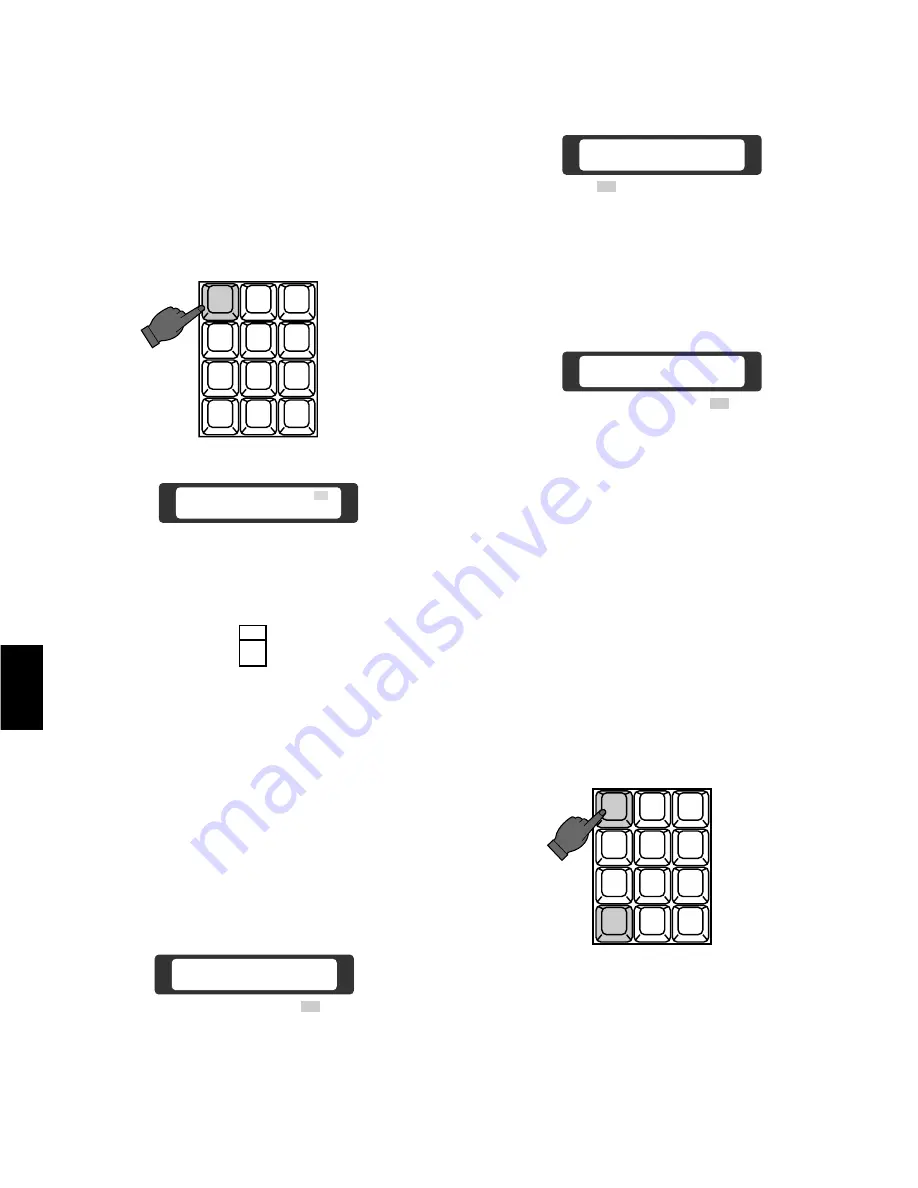
2. Select the preset number by pressing the Numeric

Keys.

2

3

4

5

6

7

8

9

MON

CAM

ESC

SET

0

1

Camera  01         1
Monitor 16

A1

3. Press the Preset 

(PRESET)

Switch to activate the

Pan/Tilt Head to move to the preset position.

PRESET

AF

6-4 Pan/Tilt Control (Camera Position Operation)

The following function is available only when the Mode
Selection Switch is selected at CAM-P Mode on the rear of
the System Controller.

1.  Select the desired monitor.

Refer to the Monitor Selection on page 98.

2. Select the CAM-P 

(D5)

Menu on the LCD by pressing

the Cursor Keys.

3. Press the Function 

(F4)

Key to display the menu

shown below.

CAM-P Menu
Set Clear Test Mode

F 1

F 2

F 3

F 4

D5

CAM-P Mode Off
On             Exit

F 1

F 2

F 3

F 4

4. Press the  Function 

(F1)

Key repeatedly to select the

On mode.

CAM-P Mode On
Off            Exit

F 1

F 2

F 3

F 4

Note:

After selected On mode on the LCD by pressing

the Function 

(F1)

Key, the Monitor 

(MON)

Key will

be activated to execute the selection.
When selecting the monitor, press the Function

(F1)

Key instead of the Monitor 

(MON)

Key while

the Camera/Monitor Selection 

(A1)

Menu is dis-

played on the LCD.

5. Press the Function 

(F4)

Key to return to the CAM-P

Menu.

6. Select the desired camera position number by press-

ing the Numeric Keys, then press the Monitor 

(MON)

Key to activate the camera to move the preset posi-
tion.

1

2

3

4

5

6

7

8

9

MON

CAM

ESC

SET

0

Note:

If operating above functions, it is required to

register the preset position number with the cam-
era number.
Refer to the Mode Selection Switch Setting on
page 56 and the Camera Position Number Setting
on page 115 for more details.

6

Summary of Contents for WJ-CU550A

Page 1: ...Before attempting to connect or operate this product please read these instructions completely Matrix Switcher WJ SX550A System Controller WV CU550A ENGLISH DEUTSCH FRANÇAIS ...

Page 2: ...LUG IS INSERTED INTO ANY 13 AMP SOCKET If a new plug is to be fitted please observe the wiring code as shown below If in any doubt please consult a qualified electrician WARNING This apparatus must be earthed IMPORTANT The wires in this mains lead are coloured in accordance with the follow ing code Green and yellow Earth Blue Neutral Brown Live As the colours of the wire in the mains lead of this ...

Page 3: ......

Page 4: ... the unit under conditions where temperatures are within 10 C 50 C 14 F 122 F and humidity is below 90 The input power source is 220 240V AC 50 Hz FEATURES The WJ SX550A Matrix Switcher when combined with the WV CU550A System Controller and WJ AD550 Extension Unit enables control of the following functions Routing of up to 128 cameras to any one of 16 moni tors Remote control of up to 128 cameras ...

Page 5: ... this section Also in depth information about each board is given here along with details about proper board setup A table is included here that specifies how many optional boards are required for every possible system expansion Section 4 Installation and System Connections Information about cable connections between the Matrix Switcher and System Controllers cameras monitors and peripheral device...

Page 6: ...AGE 11 22 3 DETAILED PRODUCT DESCRIPTION AND SELECTION PAGE 23 48 4 INSTALLATION AND SYSTEM CONNECTIONS PAGE 49 64 5 SOFTWARE SETUP PAGE 65 92 7 TROUBLESHOOTING PAGE 119 122 6 OPERATING PROCEDURES PAGE 93 118 9 INDEX PAGE 127 130 8 SPECIFICATIONS PAGE 123 126 3 TABLE OF CONTENTS 1 2 3 4 5 6 7 8 9 ...

Page 7: ... 4 ...

Page 8: ... 5 BASIC OPERATION OF A MATRIX SWITCHER 1 ...

Page 9: ... is dis played on monitor 2 In this example camera 4 and monitor 3 are also connected as well as camera 8 and monitor 4 Spot and Sequence Two basic operations of the Matrix Switcher are the SPOT and SEQUENCE functions In the SPOT mode a specific camera is continuously connected to a specific monitor with no interruption In the SEQUENCE mode a series of cameras are displayed in succession on a moni...

Page 10: ...pattern previously stored in memory and activates the crosspoint switches in the proper order For example 7 Activation of crosspoint switches Matrix Switcher SW11 SW21 SW31 SW41 SW12 SW22 SW32 SW42 SW13 SW23 SW33 SW43 SW14 SW24 SW34 SW44 SW15 SW25 SW35 SW45 SW16 SW26 SW36 SW46 SW17 SW27 SW37 SW47 SW18 SW28 SW38 SW48 Crosspoint Switch Sequence Pattern Alarm Timer Alarm 3 input e Camera 3 picture ou...

Page 11: ...ltiplexed with the video signals and is used to syn chronize Panasonic cameras to prevent picture rolling during switching between cameras Control Data Controls pan tilt zoom focus iris control shutter speed back light setting preset position auxiliary control wiper and defroster Status Data Sends camera setting information s s s SW11 SW21 SW31 SW41 SW12 SW22 SW32 SW42 SW13 SW23 SW33 SW43 SW14 SW2...

Page 12: ...implemented as shown below Light on Aux 2 Camera 1 Dwell time 1 sec Camera 4 Pre 1 Dwell time 3 sec Camera 4 Pre 2 Dwell time 2 sec Dwell time 30 sec Gate open Aux 1 s s s Camera 5 s s s Camera 6 Camera 1 Camera 4 Camera 5 Infrared sensor Aux 1 Aux 2 Receiver Pre 2 Pre 1 Matrix Switcher WJ SX 550A TL Matrix Switcher Alarm 3 MON 2 Alarm MON1 VTR Alarm Mode s s Monitor 1 Monitor 2 s t t t Camera 6 s...

Page 13: ...s seemingly complex operation can be performed by the simple settings shown in table 1 and 2 S t e p 0 1 0 1 C A M 0 4 0 4 0 5 0 2 0 3 0 4 0 1 0 2 0 1 D W E L L 0 3 0 2 3 0 A U X 2 P R E A U X 1 Table 1 Setup procedure for Tour Sequence T 1 0 3 1 2 0 6 0 3 A u t o R S T A L C A M M o d e S A U X 1 2 3 4 5 T S Table 2 Setup procedure for Alarm Activation Camera number Preset camera position Dwell t...

Page 14: ... 11 FEATURES OF THE SYSTEM 500 MATRIX SWITCHER 2 ...

Page 15: ...controllers may be connected A variety of controls are accessible through the LCD display on the system controller Also access to the Programming Set Up Menu may be gained through the system controller VCR Up to 16 VTRs can be connected The video signal controlled by the WJ SX550A Matrix Switcher is supplied to the VTR Also the Matrix Switcher can supply the VTRs with an alarm output signal to swi...

Page 16: ... system from sev eral system controllers 3 If the main power of the Matrix Switcher is turned off log in procedures must be performed again 4 If power to the system controller is turned off the sys tem controller will record operating status when power is resupplied 2 Camera and Monitor Selection After log in the desired camera and monitor combination can be selected Basically any combination of c...

Page 17: ...ontrol 4 1 Iris Control This control is used to open or close the iris of specified DC servo lens with Panasonic WV BP510 or WV CP610 series cameras 3 Camera Control The selected camera and if applicable the receiver can be controlled by the System Controller Specified Panasonic cameras such as the WV BP510 or the WV CP610 series can have various functions con trolled remotely without the need for...

Page 18: ... at the same time This control is available with the Panasonic WV CS500 or WV CS600 Combination Camera which enables the setting and recalling of the Preset function from the System Controller 6 Sequence This system has three kinds of sequential modes Program Tour and Group 6 1 Program Sequence The program sequence is a series of 64 steps assigned to a particular monitor Each step can have a speci...

Page 19: ...eps Each step has a Camera Dwell Time AUX Control and Pan Tilt Preset assigned to it A Tour can be assigned to any monitor T1 T2 T3 T4 T5 T6 T7 T8 T9 T10 T11 T12 T13 T14 T15 T16 T17 T18 T19 T20 T21 T22 T23 T24 T25 T26 T27 T28 T29 T30 T31 T32 Tour Sequence 32 Tours In Any Monitor A total of 32 Tour Sequence can be programmed with the Set Up Menu Monitor 1 Dwell time 3 sec Step 1 Monitor 1 Dwell tim...

Page 20: ...Site Alarm This alarm signal is supplied from the associated camera site receiver The applicable units for camera site alarm inputs are the WV RC100 WV RC150 and WV RC170 Receivers 2 Interface Alarm This alarm signal is supplied from the Alarm Input Connector on the optional Alarm Board installed in the WJ SX550A Matrix Switcher Up to 128 alarm inputs are available 8 2 Alarm Operation Mode There a...

Page 21: ...n Monitor One then two etc Alarm Mode 3 Any alarms to any monitors Mode 3 is a fully programmable mode Any alarm can be shown on any monitor plus sequence routines presets and auxiliary relays in receivers can be activated 8 3 Alarm Recall The WJ SX550A Matrix Switcher can store up to 99 Alarm Events in its memory The alarms may be recalled and displayed in chronological order on any desired monit...

Page 22: ... Access Access to any camera s video and control of the camera s pan tilt head may be restricted to certain operators 10 Camera Title Camera titles are available for each camera input Each title is composed of 15 characters per line times 2 lines 34341 32213 32132 Level 3 12123 Level 1 OPE 1 1 OPE 5 OPE 6 OPE 7 12341 12443 12243 Level 2 OPE 2 OPE 3 OPE 4 43432 43331 42341 Level 4 OPE 8 OPE 26 OPE ...

Page 23: ...nce CAM Camera Setting SET Setup in Displays video connected to the Video Output Board This table shows the system status in real time Possible Active modes as indicated in this table are defined below F Forward Sequence B Backward Sequence S Stopped 1 2 3 4 5 6 7 8 M1 M3 M5 M7 M9 M11 M13 M15 M2 M4 M6 M8 M10 M12 M14 M16 System Controller Partitioning To Monitors WV CU550A A L 0 2 0 3 0 5 0 6 0 7 0...

Page 24: ... On or Off mode to meet monitor requirements 14 Cable Compensation VD2 Cable Compensation This feature is used to compensate for signal loss due to cable length The most suitable position for cable loss compensation can be selected in the Set Up Menu Available cable length compensations are shown below S Up to 500m 1 600 ft M 500m 1 600 ft to 900m 2 900 ft L 900m 2 900 ft to 1 200m 4 000 ft When u...

Page 25: ...overscan parts of the display may be cut off 19 Printer A parallel printer can be used to print out the Status Alarm Recall or Set Up data The recommended printer to use is the Panasonic KX P1624 Impact Dot Matrix Printer 20 RS 232C Port This port used for connecting with a Personal Computer The memory of the WJ SX550A Matrix Switcher can be loaded or saved Also a Personal Computer can be substitu...

Page 26: ... 23 DETAILED PRODUCT DESCRIPTION AND SELECTION 3 ...

Page 27: ... more details 5 Video Output Board OUTPUT The monitors connect to this board Refer to the Video Output Board on page 32 for more details 6 Voltage Indicator 9V 5V 5V These LEDs indicate the presence of 9V 5V and 5V regulated DC voltages 7 Power On Off Switch POWER ON OFF This switch is used to turn the Matrix Switcher power on or off 8 Fuse Holder 9 Power Cord OPERATE Matrix Switcher WJ SX 550A CP...

Page 28: ...ion 1 2 Signal Ground Designation Direction 1 2 3 4 5 6 7 8 9 10 11 12 13 14 15 16 17 18 19 20 21 22 23 24 25 STROBE DATA 0 DATA 1 DATA 2 DATA 3 DATA 4 DATA 5 DATA 6 DATA 7 ACK BUSY R G B SYNC PRIM Not used Not used Ground Ground Ground Ground Ground Ground Ground Printer Switcher Printer Switcher Printer Switcher Printer Switcher Printer Switcher Printer Switcher Printer Switcher Printer Switcher...

Page 29: ...l 5 VS VD Output Connector VS VD OUT Either the VD Vertical Drive pulse or the VS Video Sync signal is provided at this connector for synchronizing other system components Note This output is a looping through output of the VS VD Input Connector These inputs and outputs are connected internal ly 6 VD Output Connector VD OUT The VD Vertical Drive pulse is provided at this connector for synchronizin...

Page 30: ...ot clearly displayed on the colour monitor Initially the B W position is selected at the factory 5 Set the jumper connector CN14 on the board for either VD Output or Status Output from the VD Output Connector Initially the VD position is selected at the factory 1 Confirm Switches SW2 on the board are set to the following positions CN13 CN12 SW4 CN14 1 2 3 4 OFF 5 6 7 8 SW2 CN14 GRAPHIC VD CN14 CN1...

Page 31: ... twisted pairs Cable length may be extended up to 1 200m 4 000 ft Designation Direction 1 2 3 4 5 6 Ground T A T B R A R B Ground Controller Switcher Controller Switcher Controller Switcher Controller Switcher 2 Test Port TEST 1 2 These ports are used only for factory test CONTROL DATA 1 DATA 2 DATA 3 DATA 4 DATA 5 DATA 6 DATA 7 DATA 8 TEST 1 TEST 2 q w 3 This board should be installed in the WJ S...

Page 32: ...ch Setting Confirm switches SW2 on the board are set to the following positions These switches are used only for factory test Always keep these switches in the OFF positions in the field Note 1 2 3 4 O F F SW2 1 2 3 4 OFF SW2 3 ...

Page 33: ... available by use of optional WV CA64 loop through cable 2 Camera Input Connector CAMERA IN 1 8 This connector accepts either a colour or B W composite video signal from the camera Also VD2 to synchronize cameras in vertical timing and data to control camera site devices such as receivers intelligent cameras and combination cameras are multiplexed through this connector 1 2 3 4 5 6 7 8 9 Not used ...

Page 34: ...1 2 3 4 OFF 1 2 3 4 OFF 1 2 3 4 OFF 1 2 3 4 OFF 1 2 3 4 OFF 1 2 3 4 OFF 1 2 3 4 5 6 7 8 9 10 11 12 13 14 15 16 1 8 9 16 17 24 25 32 33 40 41 48 49 56 57 64 65 72 73 80 81 88 89 96 97 104 105 112 113 120 121 128 CAMERA IN NO SW1 SETTING The Camera Inputs 65 to 128 are only used when the WJ AD550 Extension Unit is used The Board Number 1 to 8 should be installed in the WJ SX550A Matrix Switcher and ...

Page 35: ...synchronized with the lapse mode set in the Time Lapse VTR EXT TIMING IN 1 controls Monitor 1 output EXT TIMING IN 2 controls Monitor 2 output etc Supply the camera switching pulse from the Time Lapse VTR to this connector Minimum duration for camera switching pulse needs to be more than one 1 second RECOVER IN This connector accepts the alarm recover signal from the Time Lapse VTR q w 25 13 24 23...

Page 36: ...ite 75 ohms 1 0 Vp p PAL composite 75 ohms Signal to Noise Ratio 00 dB AGC OFF 00 dB AGC OFF ELC Shutter speed 1 60 sec 1 00 000 sec 1 50 sec 1 00 000 sec Minimum Illumination 0 008 footcandle 0 08 lux at F1 4 AGC ON Ambient Operating Temperature 00 F 000 F 00 C 00 C 00 C 000 C 00 F 00 F Dimensions 2 5 8 W x 2 3 16 H x 4 13 16 D 67 W x 55 H x 123 D mm 67 W x 55 H x 123 D mm 2 5 8 W x 2 3 16 H x 4 ...

Page 37: ...2 13 16 1 4 5 8 9 12 13 16 MONITOR OUT NO SW1 SETTING 1 2 3 4 OFF SW1 SW4 SW5 SW3 SW2 1 2 OFF SW6 SW100 SW150 SW200 SW250 CH1 OPEN C VTR 3 Set switches SW100 SW150 SW200 SW250 on the board to choose the character display mode on the monitor NOR White with Black border REV Black with White border Initially normal NOR positions are selected at the factory 4 Confirm switches SW6 on the board are set ...

Page 38: ...UX CLOSE OPEN IRIS PRESET FOCUS NEAR ZOOM TELE FAR WIDE System Controller WV CU 550 LEFT RIGHT UP DOWN ALARM BUSY F3 F4 F2 F1 CONTROLLER ON OFF IN OUT TERM ON OFF DATA 0 1 2 3 4 5 6 7 8 9 CONTROLLER UNIT NO 1 8 A AF MODE q w e r t y u i o 0 1 2 3 4 5 6 7 8 9 0 1 2 3 4 6 7 5 WV CU550A System Controller 3 ...

Page 39: ...is used to activate the preset func tion of the WV CS500 or WV CS600 Combination Camera AF This switch is used to activate the auto focus function when selected the specified camera such as the WV CS600 Combination Camera 11 Camera Key CAM Set Key SET CAM This key is used for camera selection Press the desired Numeric Keys then press this key to select the camera SET This key is used to execute th...

Page 40: ... first be selected then this switch must be pressed once for alarm acknowledgement the light blinks rapidly then this switch must be pressed once again for alarm reset After alarm acknowledgement press the Alternate ALT Switch then press this switch to reset the all acti vated alarms at once 22 Data Input Output Connectors DATA IN OUT These connectors are used to transmit receive control data to f...

Page 41: ...o the Extension Board on page 38 for more details 3 Voltage Indicator 9V 5V 5V These LEDs indicate the presence of 9V 5V and 5V regulated DC voltages 4 Power On Off Switch POWER ON OFF This switch is used to turn the Extension Unit power on or off 5 Fuse Holder 6 Power Cord OPERATE Extension Unit WJ AD 550 OFF 9V 5V 5V POWER ON 11A00001 Extension 1 2 WJ SX550A Extension 1 2 DATA ADDRESS 1 2 3 4 5 ...

Page 42: ...48E Data Board installed in the WJ AD550 Extension Unit Select the switches on the board that is installed in the WJ SX550A Matrix Switcher to the ON position to meet the Data Board Number 3 WJ SX550A Indicator WJ SX550A This indicator lights up if the board is installed in the WJ SX550A Matrix Switcher after making switch setting 4 WJ AD550 Indicator WJ AD550 This indicator lights up if the board...

Page 43: ...1 2 3 4 5 6 7 8 CAMERA IN VIDEO OUT1 VIDEO OUT2 INPUT 1 2 3 4 5 6 7 8 CAMERA IN VIDEO OUT1 VIDEO OUT2 INPUT 1 2 3 4 5 6 7 8 CAMERA IN VIDEO OUT1 VIDEO OUT2 INPUT 1 2 3 4 5 6 7 8 CAMERA IN VIDEO OUT1 VIDEO OUT2 INPUT 1 2 3 4 5 6 7 8 CAMERA IN VIDEO OUT1 VIDEO OUT2 INPUT 1 2 3 4 5 6 7 8 CAMERA IN VIDEO OUT1 VIDEO OUT2 INPUT 1 2 3 4 5 6 7 8 CAMERA IN VIDEO OUT1 VIDEO OUT2 OFF 9V 5V 5V POWER ON 11A000...

Page 44: ...eceiving alarm inputs 1 64 all at the same time Use this mode to test the system for Alarm Mode 1 Mode 2 or Mode 3 set up Mode 3 9 These modes are not available Note The alarm inputs 65 128 are activated above modes if the SW1 on the board is set at alarm number 65 128 Refer to the Dip Switch Setting on page 42 3 Test Switch TEST This switch is used to run the alarm test mode in combination with t...

Page 45: ...Alarm 40 Alarm 41 Alarm 42 Alarm 43 Alarm 44 Alarm 45 Alarm 46 Alarm 47 Alarm 48 Alarm 49 Alarm 50 Alarm 51 Alarm 97 Alarm 98 Alarm 99 Alarm 100 Alarm 101 Alarm 102 Alarm 103 Alarm 104 Alarm 105 Alarm 106 Alarm 107 Alarm 108 Alarm 109 Alarm 110 Alarm 111 Alarm 112 Alarm 113 Alarm 114 Alarm 115 20 21 22 23 24 25 26 27 28 29 30 31 32 33 34 35 36 37 Alarm 116 Alarm 117 Alarm 118 Alarm 119 Alarm 120 A...

Page 46: ...n NOR OPEN positions are selected at the factory 1 2 3 4 5 6 7 8 OFF SW4 NOR CLOSE NOR OPEN 1 1 2 3 4 5 6 7 8 OFF SW5 2 1 2 3 4 5 6 7 8 SW4 SW5 SW6 SW7 SW8 SW9 SW10 SW11 Switch No 1 8 9 16 17 24 25 32 33 40 41 48 49 56 57 64 Alarm Input Board No 1 Board No 2 WV PB5564E Alarm Board Dip Switch Setting 1 Set switches SW1 on the board to meet the alarm input number as shown below BOARD NO 1 2 OFF 1 2 ...

Page 47: ... RS 485 shielded twisted pairs Cable length may be extended up to 1 200 m 4 000 ft TB RA RB GND RT TA S W 1 DATA RS485 A T B 1 A R B G A T B 2 A R B G A T B 3 A R B G A T B 4 A R B G A T B 5 A R B G A T B 6 A R B G A T B 7 A R B G A T B 8 A R B G RT Termination Resistor 150Ω 1 2W SW Selection Switch Full Duplex Half Duplex GND Ground Connected to each channel and common ground 3 ...

Page 48: ...SW400 SW450 on the board to choose the communication lines as either Full Duplex FULL or Half Duplex HALF Initially Full Duplex FULL positions are selected at the factory 3 Set switch SW5 on the board to choose the LED indi cator as either ON or OFF mode The indicator dis plays that the control data are activated normally on the board Initially ON position is selected at the factory 4 Confirm swit...

Page 49: ...4 5 6 7 8 CAMERA IN VIDEO OUT1 VIDEO OUT2 RS 232C TIME ADJUST IN COM PRINTER OUT IN VS VD VD OUT 5 4 3 2 1 6 7 8 9 10 11 12 13 14 15 CONTROL DATA 1 DATA 2 DATA 3 DATA 4 DATA 5 DATA 6 DATA 7 DATA 8 TEST 1 TEST 2 OUT IN 1 OUT IN 2 OUT IN 3 OUT IN 4 MONITOR ALARM OUT RESET OUT EXT TIMING IN RECOVER IN OUTPUT 3 Also the extension unit has 15 slots and two Extension Boards are installed in this unit WJ...

Page 50: ...8 1 4 required 2 22 8 16 Input Boards WV PB5508E Slots Used Slots Left 3 The following table shows components required for various system configurations 1 8 9 16 17 24 25 32 33 40 41 48 49 56 57 64 5 8 5 8 5 8 5 8 5 8 5 8 5 8 5 8 not required not required not required not required not required not required not required not required 2 2 2 2 2 2 2 2 5 6 7 8 9 10 11 12 10 9 8 7 6 5 4 3 Monitors Exten...

Page 51: ...ots Left Cameras 1 8 9 16 17 24 25 32 33 40 41 48 49 56 57 64 9 12 9 12 9 12 9 12 9 12 9 12 9 12 9 12 not required not required not required not required not required not required not required not required 4 4 4 4 4 4 4 4 7 8 9 10 11 12 13 14 8 7 6 5 4 3 2 1 Monitors Extension Unit WJ AD550 Output Boards WV PB5504AE 1 2 3 4 5 6 7 8 65 72 9 12 required 8 21 9 9 73 80 9 12 required 8 22 8 10 81 88 9...

Page 52: ... 48 ...

Page 53: ... 49 INSTALLATION AND SYSTEM CONNECTIONS 4 ...

Page 54: ...ler and tighten with the four supplied screws 4 Install the System Controller with Rack Angle Brackets in the rack by using four screws procured locally Remove screws Tighten screws Rack Angle Bracket Side Panel Rack Mount Screws Rack Mount Screws Palm rest Do not block the ventilation opening or slots on the cover to prevent the unit from rising temperature Always keep the temperature in the rack...

Page 55: ...INTER OUT IN VS VD VD OUT OFF 9V 5V 5V POWER ON 11A00001 INPUT 1 2 3 4 5 6 7 8 CAMERA IN VIDEO OUT1 VIDEO OUT2 INPUT 1 2 3 4 5 6 7 8 CAMERA IN VIDEO OUT1 VIDEO OUT2 INPUT 1 2 3 4 5 6 7 8 CAMERA IN VIDEO OUT1 VIDEO OUT2 INPUT 1 2 3 4 5 6 7 8 CAMERA IN VIDEO OUT1 VIDEO OUT2 INPUT 1 2 3 4 5 6 7 8 CAMERA IN VIDEO OUT1 VIDEO OUT2 INPUT 1 2 3 4 5 6 7 8 CAMERA IN VIDEO OUT1 VIDEO OUT2 INPUT 1 2 3 4 5 6 7...

Page 56: ... OUT IN 3 OUT IN 4 MONITOR ALARM OUT RESET OUT EXT TIMING IN RECOVER IN OUTPUT Extension 1 2 DATA ADDRESS 1 2 3 4 5 6 7 8 ON OFF WJ SX550A WJ AD550 INPUT 1 2 3 4 5 6 7 8 CAMERA IN VIDEO OUT1 VIDEO OUT2 INPUT 1 2 3 4 5 6 7 8 CAMERA IN VIDEO OUT1 VIDEO OUT2 INPUT 1 2 3 4 5 6 7 8 CAMERA IN VIDEO OUT1 VIDEO OUT2 INPUT 1 2 3 4 5 6 7 8 CAMERA IN VIDEO OUT1 VIDEO OUT2 INPUT 1 2 3 4 5 6 7 8 CAMERA IN VIDE...

Page 57: ...00 5 RESET MODE 33 64 ALARM TEST 1 32 00 5 RESET MODE OFF 9V 5V 5V POWER ON 11A00001 OUT IN 1 OUT IN 2 OUT IN 3 OUT IN 4 MONITOR ALARM OUT RESET OUT EXT TIMING IN RECOVER IN OUTPUT MONITOR ALARM OUT RESET OUT EXT TIMING IN RECOVER IN MONITOR ALARM OUT RESET OUT EXT TIMING IN RECOVER IN OUT IN 1 OUT IN 2 OUT IN 3 OUT IN 4 OUTPUT OUT IN 1 OUT IN 2 OUT IN 3 OUT IN 4 OUTPUT OUT IN 1 OUT IN 2 OUT IN 3 ...

Page 58: ... SX550A Matrix Switcher is less than 1 200m 4 000 ft when using 5C 2V coaxial cable or equivalent Connection with the Camera Sites INPUT 1 2 3 4 5 6 7 8 CAMERA IN VIDEO OUT1 VIDEO OUT2 Camera 1 4 Camera 5 8 Video Input Board WV CA64 VIDEO ACTIVE LOOP THROUGH OUT WV CA64 VIDEO ACTIVE LOOP THROUGH OUT WV 7140 WV 7141 WV 7140 WV 7141 WV 7225 WV 7260D WV 7260D WV RC100 WV RC150 AUX Alarm WV RC150 AUX ...

Page 59: ...RECOVER OUT 4 ALARM OUT 5 1 SHOT IN 6 7 TAPE END OUT 8 WARNING OUT 9 HUMID OUT 10 REC OUT 11 REC REVIEW OUT 12 SERIES REC IN 13 14 TIME ADJUST IN 15 TIME ADJUST OUT 16 COM SERIES REC OUT 1 3 5 7 9 11 13 15 OUT IN OUT IN OUT IN OUT IN MONITOR ALARM OUT RESET OUT EXT TIMING IN RECOVER IN OUTPUT 1 2 3 4 Connection with the Monitors Video Output Board Monitor Monitor Monitor Monitor CAMERA SW OUT VTR ...

Page 60: ...ontroller is located on the rear of the System Controller Select the switches to meet the system shown below If the cable to be used is assembled from locally pro cured materials it is important that only high quality data grade cable suitable for RS 485 2 shield twist ed pairs is used Low grade cable will result in unstable operation of the system 4 Normal Mode Selects the menus except the CAM P ...

Page 61: ...T NO 1 8 Controller 8 Control Board Matrix Switcher WJ SX550A CONTROL DATA 1 DATA 2 DATA 3 DATA 4 DATA 5 DATA 6 DATA 7 DATA 8 TEST 1 TEST 2 ON Termination Switch Controller 1 ON ON ON ON ON ON ON Any Number 1 8 Any Number 1 8 Any Number 1 8 Any Number 1 8 Any Number 1 8 Any Number 1 8 Any Number 1 8 Any Number 1 8 Controller 2 Controller 3 Controller 4 Controller 5 Controller 6 Controller 7 Contro...

Page 62: ...er 3 IN OUT TERM ON OFF DATA 0 1 2 3 4 5 6 7 8 9 CONTROLLER UNIT NO 1 8 Controller 4 Control Board Matrix Switcher WJ SX550A CONTROL DATA 1 DATA 2 DATA 3 DATA 4 DATA 5 DATA 6 DATA 7 DATA 8 TEST 1 TEST 2 Daisy Chain Connections Termination Switch Controller Unit Number Controller 1 OFF OFF OFF ON 1 2 3 4 Controller 2 Controller 3 Controller 4 Note Do not use the 0 or 9 controller unit num bers Note...

Page 63: ...mber on the status monitor is deter mined by the Control Board port number Controller Unit Number Controller Number on Status Monitor IN OUT TERM ON OFF DATA 0 1 2 3 4 5 6 7 8 9 CONTROLLER UNIT NO 1 8 Controller 1 IN OUT TERM ON OFF DATA 0 1 2 3 4 5 6 7 8 9 CONTROLLER UNIT NO 1 8 Controller 2 IN OUT TERM ON OFF DATA 0 1 2 3 4 5 6 7 8 9 CONTROLLER UNIT NO 1 8 Controller 3 IN OUT TERM ON OFF DATA 0 ...

Page 64: ...larm 87 Alarm 88 Alarm 89 Alarm 90 Alarm 91 Alarm 92 Alarm 93 Alarm 94 Alarm 95 Alarm 96 Not used Not used Not used Ground Ground Pin No Designation Pin No Designation Board No 1 Board No 2 Board No 1 Board No 2 1 2 3 4 5 6 7 8 9 10 11 12 13 14 15 16 17 18 19 Alarm 33 Alarm 34 Alarm 35 Alarm 36 Alarm 37 Alarm 38 Alarm 39 Alarm 40 Alarm 41 Alarm 42 Alarm 43 Alarm 44 Alarm 45 Alarm 46 Alarm 47 Alarm...

Page 65: ... e O f f 1 9 2 0 0 9 6 0 0 1 9 2 0 0 1 9 2 0 0 1 2 0 0 1 9 2 0 0 1 9 2 0 0 1 9 2 0 0 F u l l H a l f F u l l F u l l F u l l F u l l F u l l F u l l C a m e r a I n O f f O f f B o a r d A d d r 1 Communication Unit Number 1 Baud Rate 19200 Data Bit 8 Parity Check None Stop Bit 1 Xon Xoff Not Use Wait Time Off Delay Time Off Alarm Data Off Return Direct Connection between the Data Board and Camera...

Page 66: ...TA DATA RS485 A T B 1 A R B G A T B 2 A R B G A T B 3 A R B G A T B 4 A R B G A T B 5 A R B G A T B 6 A R B G A T B 7 A R B G A T B 8 A R B G R A R B GND T A T B GND S W SW100 150 200 250 300 350 400 450 HALF 2 lines Internal Switch SW5 2 lines TA TB RA RB GND 1 TA TB RA RB GND 2 TA TB RA RB GND 3 TA TB RA RB GND 4 TA TB RA RB GND 5 TA TB RA RB GND 6 TA TB RA RB GND 7 TA TB RA RB GND 8 Combination...

Page 67: ... RB GND RXD TA DATA RS485 A T B 1 A R B G A T B 2 A R B G A T B 3 A R B G A T B 4 A R B G A T B 5 A R B G A T B 6 A R B G A T B 7 A R B G A T B 8 A R B G R A R B GND T A T B GND S W SW100 150 200 250 300 350 400 450 FULL 4 lines Internal Switch SW5 4 lines TA TB RA RB GND 1 2 3 4 5 8 Combination Camera Receiver R A R B GND T A T B GND R A R B GND T A T B GND R A R B GND T A T B GND R A R B GND T A...

Page 68: ...ction in a Daisy Chain Note Matrix Switcher WJ SX550A Camera In Number 4 Camera In Number 2 Set the Matrix Switcher and the Camera Controllers up to 8 shown below Models Parameters Daisy On Camera Controller WV RM70E F H Duplex Full Camera In Number 1 Unit Number 1 Unit Number 2 Camera In Number 3 Unit Number 3 Unit Number 4 Camera In Number 5 Unit Number 5 Camera In Number 6 Unit Number 6 Camera ...

Page 69: ... 65 SOFTWARE SETUP 5 ...

Page 70: ...s on the selected monitor In the Set Up Menu the following keys and switches are valid Function Keys F1 Selects the next page F2 Selects the previous page F3 Deletes or initializes the setting where the cursor is positioned F4 Opens the Pop Up Window Executes the setting or Selection Escapes from the programming mode or menu Performs various functions depending on selected menu To access the Print...

Page 71: ...r Level Table Page 82 Operator Registration Page 83 Camera Title Page 84 Alarm Recall Page 85 Status Page 85 System Controller Page 86 EXT Timing Select Page 87 Compensation VD2 Page 88 RS 485 Site Communication Page 89 Communication Speed Page 90 Clock Page 91 Set Up Programming Menu As shown below the Set Up Menu has six main sub menus Program Operator Camera Title Alarm Recall Status and System...

Page 72: ... Menu If in the example above the cursor was moved to the Program item and the Set SET Key was pressed the Program Menu would allow access to five items as shown below To select an item from the Program PROG Menu 1 Move the cursor to the desired item by moving the Joystick Controller 2 Press the Set SET Key to execute the selection The selected item appears on the monitor In this example Program S...

Page 73: ...Function F4 Key to open the Pop Up Window select Auto Skip On or Off by moving the Joystick Controller and pressing the Set SET Key to execute the selection 3 Move the cursor to the 5 position by moving the Joystick Controller Enter the desired Dwell Time 1 30 by pressing the Numeric Keys 4 Move the cursor to the 6 position by moving the Joystick Controller Enter the desired camera number 1 128 fo...

Page 74: ...umber if applicable by pressing the Numeric Keys 5 Move the cursor to the 7 position by moving the Joystick Controller Enter the desired Dwell Time 1 30 by pressing the Numeric Keys 6 Move the cursor to the 8 or 9 position by moving the Joystick Controller Press the Function F4 Key to open the Pop Up Window select AUX On or Off by moving the Joystick Controller and then pressing the Set SET Key to...

Page 75: ...position 4 by moving the Joystick controller enter the desired step number 1 64 by pressing the numeric keys 3 Move the cursor to the 5 position by moving the Joystick Controller Enter the desired Dwell Time 1 30 by pressing the Numeric Keys 4 Move the cursor to the 6 position by moving the Joystick Controller Enter the desired camera number 1 128 by pressing the Numeric Keys 5 Move the cursor to ...

Page 76: ...l D a y 1 S p e c i a l D a y 2 S p e c i a l D a y 3 S p e c i a l D a y 4 S p e c i a l D a y 5 S e t To select an item from the Timer Menu 1 Move the cursor to the desired item by moving the Joystick Controller 2 Press the Set SET Key to execute the selection The selected item appears on the monitor 3 Press the Escape ESC Key to return to the Program Menu if desired 7 Event Menu Selecting the E...

Page 77: ...by moving the Joystick Controller then enter the sequence number by pressing the Numeric Keys Next press the Set SET Key to execute the selection Note The 11 position consists of nine monitor selections 4 Move the cursor to the 12 position by moving the Joystick Controller By pressing the Set SET Key repeatedly access to higher number monitors is possible 5 Move the cursor to the 10 position by mo...

Page 78: ... desired special day S1 S5 by moving the Joystick Controller and then pressing the Set SET Key to execute the selection 3 Move the cursor to the 6 position by moving the Joystick Controller Enter the desired day by pressing the Numeric Keys 4 Move the cursor to the 7 position by moving the Joystick Controller Press the Function F4 Key to open the Pop Up Window Select the desired month by moving th...

Page 79: ... e t U p M o d e 3 A l a r m A l a r m M o d e f o r O F F S e t U p A l a r m M o d e f o r O F F S e t U p A l a r m M o d e f o r O F F S e t U p T i m e r A l a r m S c h e d u l e A l a r m M o d e f o r O F F S e t U p To select an item from the Alarm Menu 1 Select the desired item by moving the Joystick Controller 2 Press the Set SET Key to execute the selection The selected menu appears on...

Page 80: ...he Function F4 Key to open the Pop Up Window select camera site alarm input On or Off by moving the Joystick Controller and then press the Set SET Key to execute the selection 4 Move the cursor to the 7 position by moving the Joystick Controller Press the Function F4 Key to open the Pop Up Window select alarm board input On or Off by moving the Joystick Controller and then press the Set SET Key to...

Page 81: ...4 Key to open the Pop Up Window select the desired Auto Reset RST time by moving the Joystick Controller then press the Set SET Key to execute the selection Selected Time in the Window 30 60 90 120 150 180 Off In this position press the Increment INC Switch or Decrement DEC Switch repeatedly to select the Auto Reset RST time from 1 second to 60 seconds with 1 second increments or decrements 4 Pres...

Page 82: ... Key to execute the selection Selected Time in the Window 30 60 90 120 150 180 Off In this position press the Increment INC Switch or Decrement DEC Switch repeatedly to select the Auto Reset RST time from 1 second to 60 seconds with 1 second increments or decrements 4 Press the Escape ESC Key to escape from the programming mode The cursor returns to the 4 position 13 Set Up Alarm Mode 2 This table...

Page 83: ...the Joystick Controller If the spot mode was selected in step 5 enter the desired camera number 1 128 by pressing the Numeric Keys 7 Move the cursor to the 10 position by moving the Joystick Controller If the spot mode was selected in step 5 enter the desired preset number if applicable by pressing the Numeric Keys 8 Move the cursor to the 11 position by moving the Joystick Controller If the spot ...

Page 84: ...owing Alarm 2 Tour T Sequence Setup example 2 When an Alarm is activated it is able to run a desired Tour Sequence on the desired monitor if the Tour Sequence is programmed in advance Example 2 shows An Alarm 3 is activated Tout Sequence 1 runs on Monitor 2 3 Group G Sequence Setup example 3 When an Alarm is activated it is able to run the desired Group Sequence on the assigned monitor if the Grou...

Page 85: ...r then press the Set SET Key 4 Move the cursor to the 6 position by moving the Joystick Controller Press the Function F4 Key to open the Pop Up Window Select the desired alarm mode by moving the Joystick Controller then press the Set SET Key execute the selection 5 Move the cursor to the 7 8 9 or 10 position by moving the Joystick Controller Enter the desired hours military time or minutes by pres...

Page 86: ... by moving the Joystick Controller Then press the Set SET Key to execute the selection 3 Repeat the above procedures until all items have levels assigned to them 4 When completed with all level assigning press the Escape ESC Key to escape from the programming mode The cursor returns to the 3 position 16 Operator Menu The operator menu allows access to two items the level table and operator registr...

Page 87: ...hen completed this table press the Function F1 Key to select the next page Repeat the above procedures until the all operator limits are completed 8 Press the Function F2 Key to back up to the previous page 9 When satisfied with all of above steps press the Escape ESC Key to escape from the programming mode The cursor returns to the 3 position 10 Similarly repeat the above procedures to register a...

Page 88: ...e procedures until the setting up of the title for a certain camera is completed Press the Set SET Key to save the title 6 Repeat the above procedures for the rest of the cameras on this page When satisfied with the titles press the Function F1 Key to select the next page Repeat the above procedures until the titles for all cameras are completed 7 Press the Function F2 Key to go back to the previo...

Page 89: ... o d e 1 M o d e 2 M o d e 2 M o d e 2 M o d e 1 5 P a g e P a g e 1 o f 7 Press the Function F1 Key to select the next page Press the Function F2 Key to back up to the previous page Note The item Alarm indicates the description as shown below 0 Camera Site Alarm with corresponded camera number 1 Alarm Board Input with alarm input number 21 Status This table shows the system status in real time S ...

Page 90: ...fic monitors This feature prevents an operator from unintentionally gaining control over a monitor that may not be associated with their station 1 Move the cursor to the 3 position by moving the Joystick Controller then press the Set SET Key 2 Move the cursor to the desired controller and monitor position by moving the Joystick Controller Press the Increment INC Switch or Decrement DEC Switch repe...

Page 91: ... then pressing the Set SET Key to execute the selection 3 When satisfied with all settings press the Escape ESC Key to escape from the programming mode The cursor returns to the 3 position Note If External Timing is selected for a monitor any Dwell Time programmed in the sequence tables for that monitor will be invalid Minimum duration for camera switching pulse needs to be more than one 1 second ...

Page 92: ...ed and the others always select Off position 4 Repeat the above procedures until the table is completed 5 When completed this table press the Function F1 Key to select the next page Repeat the above procedures until all cam eras settings are completed 6 Press the Function F2 Key to back up to the previous page 7 When all above settings are completed press the Escape ESC Key to escape from the prog...

Page 93: ...stick Controller and then pressing the Set SET Key to execute the selection 3 Move the cursor to the 5 position by moving the Joystick Controller Enter the desired camera number for site communication by pressing the Numeric Keys and then pressing the Set SET Key to execute the selection 4 Move the cursor to the 6 position by moving the Joystick Controller Press the Function F4 Key to open the Pop...

Page 94: ...he Pop Up Window select the desired Stop Bit by moving the Joystick Controller and pressing the Set SET Key to execute the selection 7 Move the cursor to the 9 position by moving the Joystick Controller Press the Function F4 Key to open the Pop Up Window select Address Control On or Off by moving the Joystick Controller and then pressing the Set SET Key to execute the selection 8 Move the cursor t...

Page 95: ... month by moving the Joystick Controller and pressing the Set SET Key 4 Move the Cursor to the 6 position by moving the Joystick Controller Enter the desired year by pressing the Numeric Key 5 Move the cursor to the 7 position by moving the Joystick Controller Enter the desired hours military time by pressing the Numeric Keys 6 Move the cursor to the 8 position by moving the Joystick Controller En...

Page 96: ... 92 ...

Page 97: ... 93 OPERATING PROCEDURES 6 ...

Page 98: ...ayed while in the Hot Start they are not ROM Read Only Memory 2 With a Normal Start the monitor screens will be blank but with a Hot Start whatever monitor camera combinations were dis played at power off will be displayed again like a Resume function 3 If the power is turned on with a Normal Start during a Timer Event the Timer Event will not occur However if the power is turned on with a Hot Sta...

Page 99: ...tered Operator No by pressing the Numeric Keys then press the CAM SET Key Initially 1 is selected at the factory 5 Enter the registered Password five numbers by pressing the Numeric Keys Initially 12345 are selected at the factory Initial Check 9600 BPS Log in 1 2 3 4 5 6 7 8 9 MON CAM ESC SET 0 Log in Operator No 2 3 4 5 6 7 8 9 MON CAM ESC SET 0 1 Operator No Operator No 1 1 2 3 4 5 6 7 8 9 MON ...

Page 100: ... in display Monitor busy will appear on the LCD when another controller with a higher operator priority is presently controlling the monitor outputs The LCD display will automatically return to the Log in display No Entry Log in Monitor Busy Log in Log in No Entry Password Welcome Monitor Busy Operator No Password Error Operator No Error 6 ...

Page 101: ...tor mm G Seq A1 Monitor mm CAM P xxxx A1 Monitor mm A2 G Seq A B Display A3 All Mon Time Title F1 F2 F3 F4 Priority Lock A4 On Off PAuto Log out F1 F2 F3 F4 Alarm in A5 PSite PBoard F1 F2 Set Up Menu A6 On F1 Pan Action B1 PAuto PRandom Status F1 F2 F4 Cam PowerHousing B2 PCam PWiperPDef F1 F3 F4 P T Z F Iris B3 Step F1 Shutter sss C1 yyy A B F1 F3 F4 Sence Up xxxxx C2 yyyy zzzzzz A B F1 F2 F3 F4 ...

Page 102: ...creases the character contrast 99 00 b Back Light Adjustment Press the Focus FOCUS NEAR FAR Control to adjust the back light of the LCD while pressing the Cursor A D B Keys at the same time NEAR increases the back light brightness 00 99 FAR decreases the back light brightness 99 00 CAM ESC SET 1 2 3 4 5 6 7 8 9 MON 0 Camera Monitor 01 Camera Monitor 02 Camera 2 Monitor 01 A1 1 2 3 4 5 6 7 8 9 MON ...

Page 103: ...ired camera and monitor Refer to the Camera Selection and Monitor Selection on page 98 2 Press the Joystick Controller to move the Pan Tilt Head towards the desired direction If the joystick is positioned in between UP and RIGHT the Pan Tilt Head moves diagonally towards Up and Right Eight directions are available UP DOWN RIGHT LEFT UP RIGHT UP LEFT DOWN RIGHT DOWN LEFT LEFT RIGHT UP DOWN By press...

Page 104: ...Keys 3 Press the Function F4 Key to display the menu shown below CAM P Menu Set Clear Test Mode F1 F2 F3 F4 D5 CAM P Mode Off On Exit F1 F2 F3 F4 4 Press the Function F1 Key repeatedly to select the On mode CAM P Mode On Off Exit F1 F2 F3 F4 Note After selected On mode on the LCD by pressing the Function F1 Key the Monitor MON Key will be activated to execute the selection When selecting the monit...

Page 105: ...Press the Function F1 Key repeatedly to turn on or off the auto panning function Pan Action Auto Random Status F1 F2 F3 F4 B1 4 Press the Function F2 Key repeatedly to turn on or off the random panning function F1 ON Auto OFF Auto F2 ON Random OFF Random 6 6 Camera Power and Housing Control For remote camera power operation a 24V AC powered camera must be installed in the housing 1 Select the desi...

Page 106: ... Press the Stop STOP Switch to stop the Program Sequence P Seq Stop Monitor 16 STOP 5 Press the Forward Sequence FORWARD SEQ Switch to continue a sequence that was previously stopped by the Stop STOP Switch The sequence will continue in the forward direction from the step that was selected at the time the Stop Switch was pressed P Seq Monitor 16 FORWARD SEQ 6 Press the Backward Sequence BACK SEQ S...

Page 107: ...ed through the Set Up Menu As described on page 70 any one of 32 tours can be assign to any one of 16 monitors 1 Select the desired monitor Refer to the Monitor Selection on page98 2 Select the desired Tour Sequence number by press ing the Numeric Keys Camera 01 1 Monitor 16 Camera 01 Monitor 16 2 3 4 5 6 7 8 9 MON CAM ESC SET 0 1 A1 3 Press the Forward Sequence Forward SEQ Switch to run the Tour ...

Page 108: ...h to start the Tour Sequence from the beginning of the sequence pattern that was previously stopped by the Stop STOP Switch 10 To cancel the Tour Sequence select a camera Refer to the Camera Selection on page 98 SEQ ALT FORWARD 7 3 Group Sequence The following functions are available only if a Group Sequence has been previously established through the Set Up Menu As described on page 71 up to 8 Gr...

Page 109: ...16 DEC 1CAM 10 Press the Forward Sequence FORWARD SEQ Switch after pressing the Alternate ALT Switch to start the Group Sequence from the beginning of the sequence pattern that was previously stopped by the Stop STOP Switch 11 To cancel the Group Sequence select a camera Refer to the Camera Selection on page 98 6 8 Displaying Playback Video If connected the VTR s Video Output to the Monitor Input ...

Page 110: ...ly to display or erase all items from the monitor F1 07 MAY 96 14 23 56 C 01 M16 3rd Floor Pr64 Sp Room 306 6 Press the Function F4 Key repeatedly to display or erase the title 5 Press the Function F3 Key repeatedly to display or erase the date and time from the monitor F3 07 MAY 96 14 23 56 C 01 M16 3rd Floor Pr64 Sp Room 306 F4 07 MAY 96 14 23 56 C 01 M16 3rd Floor Pr64 Sp Room 306 4 Press the F...

Page 111: ...speed differs by the selected camera 4 Press the Function F1 Key to turn off the electronic shutter mode F1 F2 F3 F4 Shutter Off On Shutter On Off 10 2 Electronic Sensitivity Up Mode The following function is available only when specified cameras with the electronic sensitivity feature are used 1 Select the desired camera and monitor Refer to the Camera Selection and Monitor Selection on page 98 2...

Page 112: ...n the LCD by press ing the appropriate Cursor Keys F1 F2 F3 F4 Ele Zoom Off On Posi C3 Camera 01 Monitor 16 Key No 3 Press the Function F1 Key to select the Electronic Zoom Mode A Zoomed picture appears on the moni tor The area shown is the area that was last selected F1 F2 F3 F4 Ele Zoom Off On Posi F1 F2 F3 F4 Ele Zoom On Off Posi 4 Press the Function F3 or F4 Key repeatedly to select the desire...

Page 113: ...98 Camera 01 Monitor 16 2 Select the Cam Preset D1 Menu on the LCD by pressing the appropriate Cursor Keys F1 F2 F3 F4 Cam Preset Home F1 F2 F3 F4 F1 F2 F3 F4 Cam Preset 01 Home Cam Preset Home ON Home OFF Home 3 Press the Function F1 Key to activate the camera to move the Home Position 10 5 Back Light Compensation BLC Mode The following function is available only when specified cameras with the A...

Page 114: ... or entering sub menu and press the Escape ESC Key to escape from the setup mode or menu 5 Press the Function F2 Key to reset the selected menu and press the Function F3 Key to reset all set tings to initial state Refer to the Operating Instructions of the selected cam era for more details Note 6 Press the Function F4 Key to return to the original screen Caution If camera setup is started with swi...

Page 115: ... by press ing the appropriate Cursor Keys ALARM LED 11 Camera Status Display 1 Select the desired camera and monitor Refer to the Camera Selection and Monitor Selection on page 98 2 Select the Pan Action B1 Menu on the LCD by press ing the appropriate Cursor Keys F1 F2 F3 F4 Pan Action Auto Random Status B1 Camera 01 Monitor 16 13 3 To Cancel Alarm Single Monitor The alarmed monitor s must first b...

Page 116: ... 4 on activating the Alarm Mode 2 2 Press the Alternate ALT Switch to light up the LED indicator on the switch 3 Press the Alarm Acknowledge and Reset ACK RESET Switch once for alarm acknowledgement The LED indicator on the switch blinks rapidly 4 Press the Alarm Acknowledge and Reset ACK RESET Switch once again for alarm reset The LED indicator light turns off 14 Preset Setting WV CS500 Only The ...

Page 117: ...set Position Setting table appears on the monitor 14 3 Setting Up Preset Position After selecting the SET UP PRESET sub menu a table titled PRESET NUMBER SET appears on the monitor CAM CameraTitle PRESET NUMBER SET 1 2 3 4 5 6 7 8 9 10 11 12 13 14 15 H 16 17 18 19 20 21 22 23 24 25 26 27 28 29 30 31 32 14 2 Preset Program Menu As shown below the Preset Program Menu has three sub menus SET UP PRESE...

Page 118: ...o the Preset Program Menu 14 4 Home Position Setting After selecting the SET HOME POSI sub menu a table titled HOME POSITION appears on the monitor CAM CameraTitle HOME POSITION 1 HOME POSITION 15 2 AUTO HOME POSITION 10MIN 14 6 Clear the Preset Settings 1 Select the desired camera and monitor Refer to the Camera Selection and Monitor Selection on page 98 2 Select the Preset D3 Menu on the LCD by ...

Page 119: ...on Number by pressing the Numeric Keys When completed above steps press the Set SET Key to execute the selection If made mistake on the above steps press the Escape ESC Key to cancel the selection 15 2 Delete Camera Position Number 1 Select the desired monitor Refer to the Monitor Selection on page 98 2 Select the CAM P D5 Menu as shown below on the LCD by pressing the appropriate Cursor Keys Note...

Page 120: ... position number operation when the camera position mode is selected at On mode 1 Select the CAM P D5 Menu shown below on the LCD by pressing the appropriate Cursor Keys CAM P Menu Set Clear Test Mode F1 F2 F3 F4 D5 CAM P Mode Off On Exit F1 F2 F3 F4 3 Press the Function F4 Key to display shown below on the LCD Press the Function F1 Key repeatedly to select the mode On or Off 4 Press the Function ...

Page 121: ...may still gain control of that monitor 17 Log Out This function is used when an operator is leaving the con troller or no longer requires access to the system Controlling any functions from this controller is restricted until an operator logs in 1 Select the Log Out A4 Menu by pressing the appro priate Cursor Keys 2 Press the Function F4 Key to log out The LCD dis play shows the Log in Display Log...

Page 122: ... 118 ...

Page 123: ... 119 TROUBLESHOOTING 7 ...

Page 124: ...he camera in question 2 If a monitor cannot be have any camera selected check the Controller Table and make sure that controller can con trol the output of the monitor 3 Check if the monitor has a Priority Lock set by another operator 4 If the camera can be displayed on another monitor there may be a problem with the Video Output Board call quali fied service personnel Symptom No Pan Tilt Zoom con...

Page 125: ... Key to clear display Change the operator s level and or video lockout setup Symptom WARNING PROHIBITED appears on the monitor screen 1 The System Controller is not allowed to access a particular monitor due to Keyboard Monitor partitioning Change Keyboard Monitor partitioning in the Set Up Menu Symptom When Log in is attempted No Entry appears on the LCD 1 An incorrect password or operator number...

Page 126: ...il the other operation is made after the stop time Symptom The Group Sequence does not run to synchronized on the monitors that is made the EXT Timing setting from the connected VTR 1 The step switching on the Group Sequence depends on the EXT Timing on a lowest number of the monitors that are assigned to run the Group Sequence Symptom Can t operate the cameras by the Camera Position Numbers 1 Che...

Page 127: ... 123 SPECIFICATIONS 8 ...

Page 128: ...larm Recalls 99 Alarm Activations Mode 1 Any alarms to 1 monitor Mode 2 Any alarms to 4 monitors Mode 3 Any alarms to any monitors max 110 patterns Time Alarms Start Step 10 day Formats of Time Alarm Program Day of week 5 special days Operator Set Up Max Operator Registrations 30 operators with 5 digits password and priority Access Operator Levels 5 levels Ambient Operating Temperature 10 C 50 C 1...

Page 129: ...0 D mm 15 16 W x 10 7 16 H x 10 1 4 D Weight 400g 0 9 lbs WV CU550A System Controller Power Supply 220 240V AC 50 Hz Power Consumption Approx 4W Data Input Output 6 conductor Modular Jack RS 485 4 Lines Switching Functions Program Sequence Tour Sequence Group Sequence Backward Sequence Forward Sequence Inc Dec Camera Functions Electronic Shutter On Off Shutter Speed Select Electronic Sensitivity U...

Page 130: ...ft Max Number Boards 8 Address 1 8 Total 1 64 Data Input Output Dimensions 24 5 W x 265 H x 260 D mm 15 16 W x 10 7 16 H x 10 1 4 D Weight 400g 0 9 lbs WV Q62E Rack Angle Bracket Dimensions 90 W x 177 H x 30 D mm 3 9 16 W x 6 15 16 H x 1 3 16 D Weight 720g 1 6 lbs WV Q63E Blank Panel Dimensions 25 4 W x 263 H x 6 D mm 1 W x 10 3 8 H x 1 4 D Weight 50g 0 1 lbs Weight and dimensions shown are approx...

Page 131: ... 127 9 INDEX ...

Page 132: ...nput Connector 30 54 Camera Key 35 98 Camera Position Number 115 Camera Selection 14 98 Camera Setting 20 85 CAM P Menu 100 115 116 CAM P Mode 97 100 115 Camera Set Up Menu 110 Camera Site Alarm 17 Camera Status 111 Camera Title 19 67 84 Cam Power and Housing Menu 101 Cam Preset Menu 109 Character 84 Character Table 84 Clock 22 Clock Set 91 Combination Connection 59 Communication Speed 21 67 90 Co...

Page 133: ...or Selection 13 98 N Numeric Key 35 O On Screen Display 22 Operator Level 13 19 82 83 Operator Limit 19 83 Operator Menu 82 Operator Number 13 83 95 96 Operator Resistration 19 67 82 83 P Pan Tilt Control 14 99 100 101 Pan Action Menu 101 111 Partitioning 20 21 Password 13 19 83 95 96 Position Number 114 Preset BLC Mode 110 Preset BLC Setting 113 Preset Control 15 Preset Menu 112 Preset Number 113...

Page 134: ...tus 20 85 T Termination Switch 36 57 58 59 Test Port 28 Test Switch 40 Time Adjustment Input Connector 25 Time Lapse Mode 87 Time Lapse VTR 16 25 32 87 Timer 7 17 67 Timer Alarm Schedule 81 Timer Event Schedule 73 74 Timer Menu 72 Title 84 106 Title Display 106 Tour Sequence 10 16 20 67 70 72 73 85 103 V VD 26 27 VD Output Connector 26 27 VD VS Selection Switch 26 VD2 8 21 30 88 Video Input Board ...

Page 135: ... 131 ...

Page 136: ...n abdeckung angegeben Sie sollten die Fabriknummer dieses Gerätes in den dafür vorgesehenen Raum eintragen und diese Anleitung als Kaufsunterlage aufbewahren um im Falle eines Diebstahls die ldentifizierung zu erleichtern Modellnummer Fabriknummer WARNUNG UM DIE GEFAHR VON BRAND ODER STROMSCHLAG ZU VERHÜTEN DIESES GERÄT WEDER REGEN NOCH FEUCHTIGKEIT AUSSETZEN WARNUNG WEDER DECKEL NOCH RÜCKPLATTE A...

Page 137: ......

Page 138: ...N0396 0156 YWV8QA4204BN Printed in Japan N 19 Gedruckt in Japan Imprimé au Japon Matsushita Electric Industrial Co Ltd Central P O Box 288 Osaka 530 91 Japan ...

Reviews: