Design of 3WAY VRF SYSTEM
2
- 52
8
7
6
5
4
3
2
1
7. Optional Parts
Solenoid Valve Kit
CZ-P56HR1U
CZ-P160HR1U
Indoor Unit Capacity
7 -18 Type
24 - 48 Type
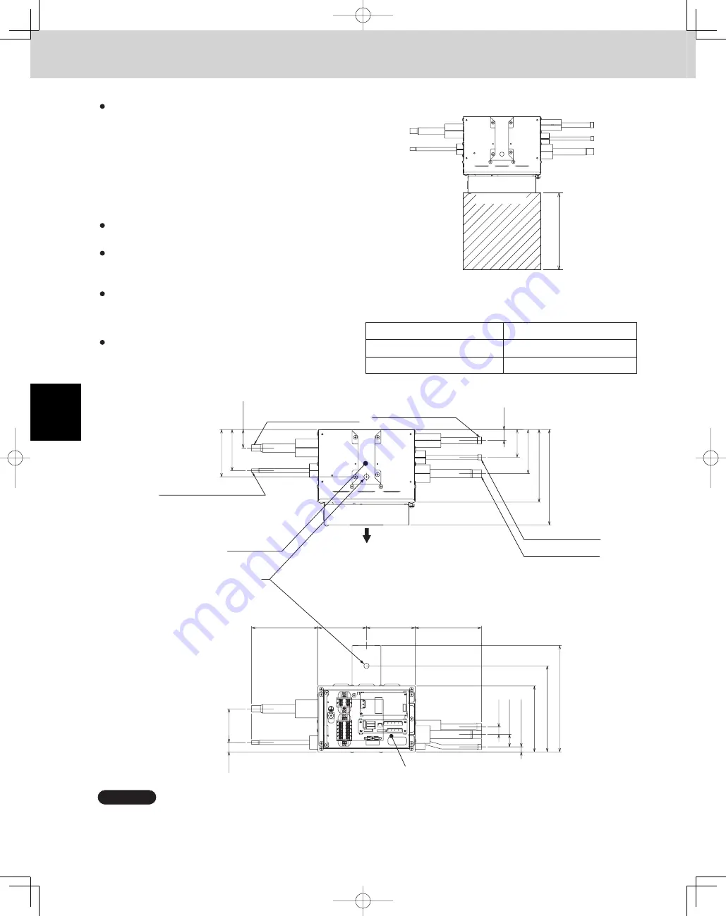
3. Valve Dimensions and Hanging Method
There are 2 types of solenoid valve kits: type 56
and type 160. The corresponding indoor unit model
capacities are shown in the table at right.
This figure shows the unit with suspension fittings attached.
Be sure to secure the solenoid valve kit to the
structure and the hanging bolts, etc. using the top or
side holes of the hanging hooks. Do not place the
solenoid valve kit directly on the ceiling surface.
When installing the solenoid valve kit,
remember to
install it with the top surface facing upward.
(See the figure shown in the subsection "How to use
the fittings" in " 3. Valve Dimensions and Hanging
Method.")
Provide a service space of 7-7/8" or more in front
of the installing site.
Never conduct drilling or welding on the sheet
metal.
Place the solenoid valve kit so that it does
not hinder draining.
Do not cover air holes.
Service space
5-55/64
53/64
2-63/64
9-29/64
63/64
2-31/64
3-15/16
6-29/64
8-15/32
5-55/64
7-41/64
7/16
1-7/64
43/64
4-21/64
4-21/64
5-55/64
4-7/32
1-21/32
3-21/32
Gas tube ID 1/2" ( 5/8" )
Discharge tube ID 1/2"
Hanging hook
Liquid tube ID 3/8"
Front side
Cover of electrical components
Suction tube ID 5/8"
Liquid tube ID 1/4" ( 3/8" )
Holes for suspension bolt ø15/32
7-7/8" or more
Front side
unit : in.
NOTE
TD831158-00̲3WAY̲VRF̲SYS.indb 52
TD831158-00̲3WAY̲VRF̲SYS.indb 52
2012/01/23 17:30:21
2012/01/23 17:30:21
Summary of Contents for U-72MF1U9
Page 118: ...Section 8 TENTATIVE ...


