


Design of 3WAY VRF SYSTEM
2
- 50
8
7
6
5
4
3
2
1
7. Optional Parts
NOTE
Cut off as far away from stopper as possible.
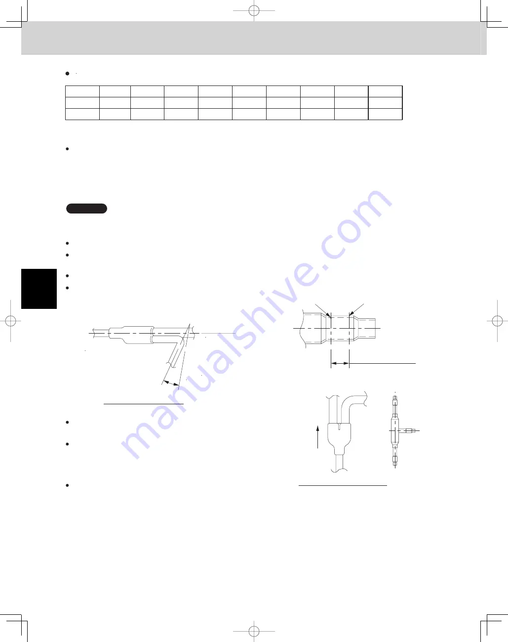
3. Making Branch Connections
Avoid forceful cutting that may harm the shape of the joints or tubing.
(Inserting the tubing will not be possible if the tube shape is not proper.)
Stopper (boss)
Cutting point
The distribution joint can be either horizontal or vertical.
In the case of horizontal, the L-shaped tubing must be
slanted slightly upward (15° to 30°).
After cutting the joints,be sure to remove burrs on the inside of the joints.
(If the joints have been squashed or dented badly, reshaped them using a tube spreader.)
Using a tube cutter,cut the joints at the diameter required to match the outside diameter of the tubing you are
connecting.
(This is usually done at the installation site.) The tube diameter depends on the total capacity of the indoor unit.
Note that you do not have to cut the joints if it already matches the tubing end size. For size selection of the tube
diameter, refer to the installation instructions provided with the outdoor unit.
Insertion length of the
connecting tube
Make this as long as
possible.
Make sure there is no dirt or other foreign substances inside the distribution joint.
To insulate the distribution joint, use the supplied tubing
insulation.
(If using insulation other than that supplied, make sure
that its heat resistance is 248˚F or higher.)
When brazing,replace air inside the tube with nitrogen gas to
prevent copper oxide from forming.
For additional details, refer to the installation instructions
provided with the outdoor unit.
Outdoor unit
Side
15 to 30°
upward slant
Indoor unit
Side
(directed upward or downward)
In case of horizontal position
In case of vertical position
Size of connection point on each part (Shown are inside diameters of tubing)
Size
Part D
E
t
r
a
P
A
t
r
a
P
H
t
r
a
P
B
t
r
a
P
Part G
Part I
F
t
r
a
P
C
t
r
a
P
mm
Ø25.4
2
2
.
2
2
Ø
1
.
8
3
Ø
7
.
2
1
Ø
3
9
.
4
3
Ø
Ø15.88
Ø9.52
5
0
.
9
1
Ø
8
5
.
8
2
Ø
Inch
1
8
/
7
2
/
1
-
1
2
/
1
4
/
1
-
1
5/8
3/8
4
/
3
8
/
1
-
1
TD831158-00̲3WAY̲VRF̲SYS.indb 50
TD831158-00̲3WAY̲VRF̲SYS.indb 50
2012/01/23 17:30:21
2012/01/23 17:30:21
Summary of Contents for U-72MF1U9
Page 118: ...Section 8 TENTATIVE ...


