


Design of 3WAY VRF SYSTEM
2
- 34
8
7
6
5
4
3
2
1
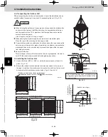
4. Installation Instructions
4-6. Dimensions of Wind Ducting
Reference diagram for air-discharge chamber (field supply)
33-3/16
33-3/16
33-3/16
33-3/16
2
1
106-1/8
106-1/8
106-1/8
74-1/16
74-1/16
74-1/16
(32-1/8)
(32-1/8)
35-1/4
35
(Ceiling panel dimensions)
33-1/4
35-1/4
35
(Ceiling panel dimensions)
35
(Ceiling panel dimensions)
2
1
(32-1/8)
35
(Ceiling panel dimensions)
Ceiling panel
Ceiling panel
Note:
31-1/8
5-3/4
5-3/4
113
74-1/4
7-7/8
7-7/8
36-1/4
(Installation hole pitch)
2
1
35
(Ceiling panel dimensions)
3-unit installation
(Installation hole pitch)
31-1/8
(Installation hole pitch)
31-1/8
(Installation hole pitch)
Air direction: Front direction
Air direction: Right direction
unit: in.
unit: in.
(Maximum bracket dimensions)
(Maximum bracket dimensions)
Front view
Right side view
Front view
Right side view
Can be installed so that the air direction is to the front, right, left or rear direction.
(3-unit installation: maximum dimensions)
Top view
(2-unit installation: maximum dimensions)
Front view
Right side view
TD831158-00̲3WAY̲VRF̲SYS.indb 34
TD831158-00̲3WAY̲VRF̲SYS.indb 34
2012/01/23 17:30:18
2012/01/23 17:30:18
Summary of Contents for U-72MF1U9
Page 118: ...Section 8 TENTATIVE ...


