


Design of 3WAY VRF SYSTEM
2
- 15
1
2
3
4
5
6
7
8
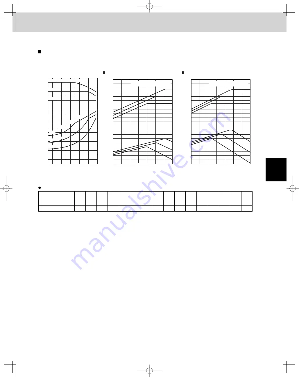
1. Model Selecting and Capacity Calculator
1-9. Capacity Correction Graph According to Temperature Condition
Capacity characteristics
(The corrected capacity for specifi c temperature conditions can be found from the graphs below.)
Indoor air intake temp. (WB) = 71 F
Indoor air intake temp. (WB) = 71 F
WB = 67°F
WB = 61°F
WB = 67°F
Indoor air intake temp. (WB) = 72°F
Indoor air intak
e temp
. (WB) = 72°F
WB = 61°F
Capacity r
atio (%)
Input r
atio (%)
80
90
100
120
130
80
70
60
50
40
30
20
10
14 23 32 41 50 59 68 77 86 95 104 113
90
100
120
6-Ton
8-Ton
< Cooling >
< Heating >
130
120
100
90
80
70
60
50
40
130
120
100
90
80
70
60
50
- 4
5
14
23
32
41
50
59
61
70
79
61
70
79
Indoor air intake temp. (°F DB)
- 4
5
14
23
32
41
50
59
130
120
100
90
80
70
60
50
40
130
120
100
90
80
70
60
50
61
70
79
61
70
79
Indoor air intake temp. (°F DB)
Capacity r
atio (%)
Input r
atio (%)
Capacity r
atio (%)
Input r
atio (%)
110
110
110
110
110
110
Heating capacity correction coeffi cients for frost/defrost operation
Outdoor intake air
temp.
(°F WB RH85%)
– 4
5
14
17
21
23
24
28
30
32
33
35
37
39
41
42
Correction coefficient
0.97
0.97
0.97
0.96
0.94
0.91
0.89
0.87
0.87
0.87
0.88
0.89
0.91
0.92
0.95
1.0
*
The heating capacity when frost/defrost operation is considered is calculated by multiplying the heating capacity found
from the capacity graph by the correction coeffi cient from the table above.
TD831158-00̲3WAY̲VRF̲SYS.indb 15
TD831158-00̲3WAY̲VRF̲SYS.indb 15
2012/01/23 17:30:13
2012/01/23 17:30:13
Summary of Contents for U-72MF1U9
Page 118: ...Section 8 TENTATIVE ...


