


Design of 3WAY VRF SYSTEM
2
- 37
1
2
3
4
5
6
7
8
4. Installation Instructions
Fig. 2-18
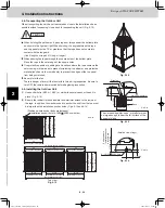
4-10. Remove the Brackets Used for Transport
After installing the unit, remove the
2 transport brackets from the front
and rear (4 brackets total).
(Fig. 2-16)
Remove the 2 screws
(8 screws total)
Remove the 2 transport brackets from
the front and rear (4 brackets total)
Fig. 2-17
Fig. 2-16
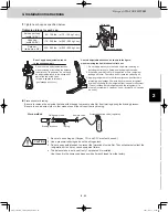
4-11. Routing the Tubing
The tubing can be routed out either from the front or from the bottom. (Fig. 2-17)
The connecting valve is contained inside the unit. Therefore, remove the front panel. (Fig. 2-17)
(1) If the tubing is routed out from the front, use cutting pliers or a similar tool to cut out the tubing outlet slit (part
indicated by
) from the tubing cover. (Figs. 2-17 and 2-18)
(2) If the tubing is routed out from the bottom, remove
the slit part (
).
Use a drill bit approximately 13/64" dia. to create
holes at the 4 slit hole indentations (openings).
Punch out the slit part (
).
Be careful not to damage the base plate.
Remove 2 screws
Tubing cover
Bottom
Front
Remove 11 panel
screws from front
panel
Use cutting pliers or similar
tool to cut cover out
Indentation
(4 locations)
Slit hole
TD831158-00̲3WAY̲VRF̲SYS.indb 37
TD831158-00̲3WAY̲VRF̲SYS.indb 37
2012/01/23 17:30:18
2012/01/23 17:30:18
Summary of Contents for U-72MF1U9
Page 118: ...Section 8 TENTATIVE ...


