8. Motion Detection Setting (MOTION DET)
When a series of changes in pictures is detected, the camera outputs an alarm to the exter-
nal device such as a disk recorder. The recorder will start recording the pictures.
1. Select a mode for MOTION DET on the CAMERA SETUP menu.
The default setting is OFF.
OFF:
Disables the alarm output.
MODE1
↓
:
Outputs alarm when a series of
motions is detected.
MODE2:
Outputs alarm when a series of
scene changes is detected.
→
The MODE 1 menu opens when you
select MODE1 and press SET .
2. Adjust for LEVEL to optimize the sensitivity of
detection.
3. Select a dwell time. The default is 2S.
Available time (second):
2, 5, 10, 30
The next detection will be performed after
the set time elapses.
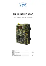
4. Select MASK SET and press SET.
→
A 48-split screen opens.
• Specify non-detection (mask) and detection
areas in the same way as described earlier
in 2.2 ELC Mode.
• Hold down SET for 2 seconds to return to the MOTION DET menu.
Note:
Perform the setting of mask area after STABILIZER in the CAMERA SETUP menu is
set to OFF.
5. Select ON or OFF for ALARM under DISPLAY MODE.
ON:
Outputs an alarm
OFF:
Does not output an alarm. This is applicable any of the following controllers are
used: WV-RM70, WV-CU550 series, WV-CU161, WV-CU360, WV-CU650, WV-CU850,
WV-CU950
6. Select DISPLAY MODE and press SET to see the current settings.
When a motion is detected, the area will blink.
• Press SET to return to the MODE1 menu.
7. As necessary, repeat to perform LEVEL adjustment and MASK setting by checking on the
DISPLAY MODE screen.
Notes:
• In systems other than Panasonic, select OFF for MOTION DET to prevent system
devices from confusing time-code signal with alarm signal.
• Set MASK SET over the areas where leaves or curtains etc. are swaying.
• Adjust the detection level to prevent detection from confusing motion with noise under
low light conditions.
• It takes about 0.2 seconds for the alarm signal to reach the VCR’s alarm terminal after
detection.
• The motion/scene change detection is not specifically intended to prevent theft or fire.
9. Digital Noise Reduction Setting (DNR)
Select a DNR mode suitable to the camera site conditions. The default setting is HIGH.
HIGH:
Greatly reduces noise, though it produces afterimages when objects move.
LOW:
Slightly reduces noise, and produces less afterimages.
10. Resolution Setting (RESOLUTION)
Select a horizontal resolution mode. The default setting is HIGH.
NORMAL:
Resolves more than 480 TV lines.
HIGH:
Resolves typically 540 TV lines, though noise may increase when SENSE UP is
activated in low lighting conditions.
11. Black and White Mode Setting (BW MODE)
1. Select BW MODE on the CAMERA SETUP menu and press SET.
→
The BW MODE menu opens.
2. Select a mode for BW. The default setting is OFF.
AUTO1:
Sets the mode to black-and-white if the picture is dark or to color if the picture is
bright enough.
AUTO2:
Functions the same as AUTO1, except this is applied to the use near infrared
light. (wavelength
≥
800nm).
EXT:
Sets the mode to black-and-white if the sensor connected to the Day/Night IN termi-
nal is activated.
ON:
Sets the mode to black-and-white.
OFF:
Sets the mode to color.
Notes:
• There may be cases where AUTO1 or AUTO2 does not function well if the camera is
aimed at subjects continuously moving or a scene filled with a single color such as a
blue sky.
• It is possible to set up the back-focus mode to compensate for defocus liable to hap-
pen when the camera automatically switches between the color and black-and-white
modes. Refer to "16. Back-focus Setting" for details.
→
When AUTO1 or AUTO2 is selected,
LEVEL and DURATION TIME appear.
3. Select a threshold LEVEL to switch between
the color and black-and-white mode. The
default setting is HIGH.
HIGH:
Switches the mode at around 5 lux
illumination.
LOW:
Switches the mode at around 1 lux
illumination.
4. Select a duration time to determine whether to switch the mode. The default setting is 30
seconds.
Available time:
(Short) 10 s
↔
30 s
↔
60 s
↔
300 s (Long)
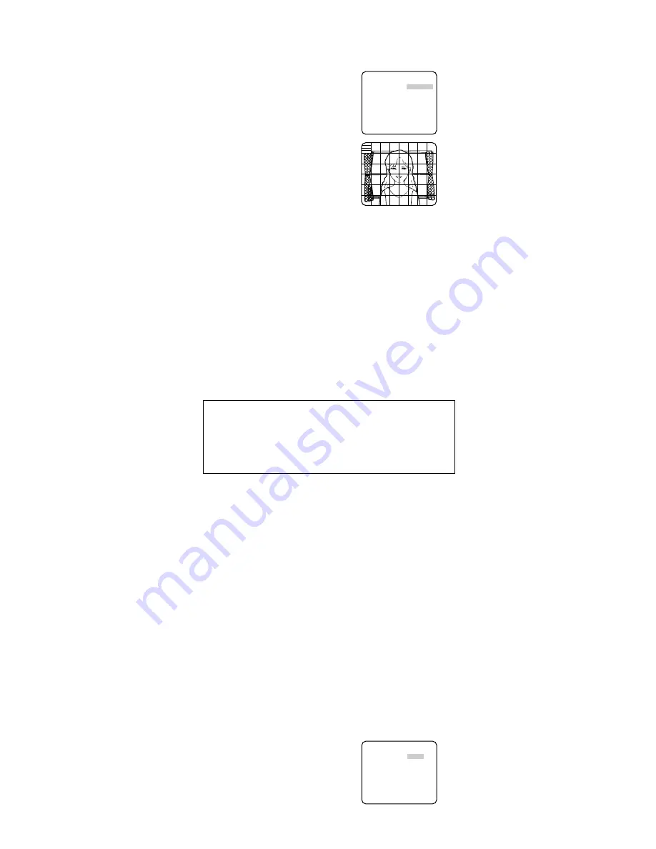
**BW MODE**
BW AUTO1
LEVEL HIGH
DURATION TIME .I..
S L
BURST(BW) ON
RET TOP END
** MODE1 **
LEVEL ........I
- +
DWELL TIME 2S
DISPLAY MODE
ALARM OFF
MASK SET
RET TOP END
↵
↵
About MODE2 of Motion Detection
• The camera will detect a scene change in the following cases.
When the lens is fully sprayed or covered with a cloth, lid, or the like
When the camera direction is suddenly changed
• The camera will not detect a scene change in the following cases.
When a cloth with patterns covers the lens and it sways in the wind
When some portions in the screen are not veiled
When the screens are similar in scene patterns although the camera direction has changed
• The camera will faultily detect a scene change in the following cases.
When an obvious brightness change arises (ex. On/Off of the lamps)
When objects move continuously such as traffic in busy streets