


5. Select a burst signal mode. The default setting is ON.
ON:
Supplies the (color) burst signal with black-and-white composite video.
OFF:
Supplies no burst signal.
Note:
Using ON is usually recommended. Try both ON and OFF to match to connected
devices (recorders, monitors, etc.) that have different characteristics.
12. Privacy Zone Setting (PRIVACY ZONE)
Perform settings of up to eight privacy zones where you wish to veil the monitor screen.
1. Select ON(1), ON(2) or OFF for PRIVACY ZONE on page 2 of the CAMERA SETUP menu
and press SET. The default setting is OFF.
ON (1):
Veils the zone with gray.
ON (2):
Veils the zone with mosaic.
OFF:
Displays pictures normally.
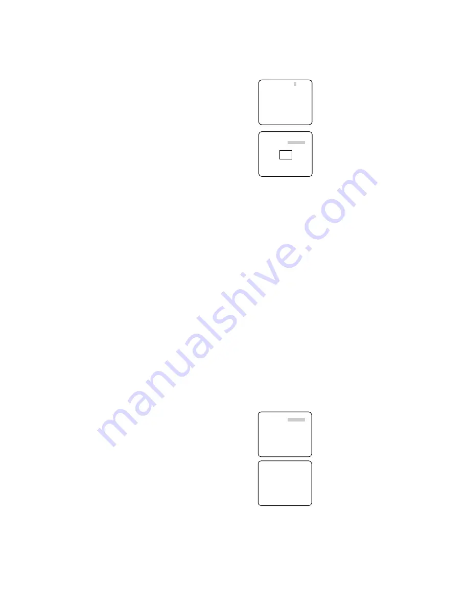
→
The ZONE NUMBER selection menu
opens.
2. Select a zone number on the top line using
L/R buttons and press SET. The zone num-
ber followed by an asterisk * indicates that
it has been already registered.
→
POSITION, SCALE, and a frame appear
on the menu.
3. Select
→
PUSH SW for POSITION and
press SET.
→
Position selection becomes available.
4. Move the picture portion to be veiled to the
center of the frame using the L/R/U/D but-
tons.
5. Select
→
PUSH SW for SCALE and press SET.
→
Zone scale adjustment becomes available.
6. Adjust the zone scale using the L/R/U/D buttons.
7. To apply the settings, move the cursor to SET and press SET.
→
The screen returns to the ZONE NUMBER selection menu.
To delete the settings, select DEL and press SET.
13. Mirror Setting (MIRROR)
Specify whether to horizontally reverse the camera picture. The default setting is OFF.
OFF:
Displays pictures normally.
ON:
Displays pictures horizontally reversed.
14. Lens Drive Signal Selection (LENS-DRIVE)
Select the suitable drive type for the auto iris lens mounted. The default setting is DC.
DC:
Is used for DC drive type lens.
VIDEO:
Is used for video drive type lens.
15. Auto Image Stabilizer (STABILIZER)
This function electronically compensates for an unstable camera image due to movement of
a mounting pole or bracket. The default setting is OFF.
ON:
Automatically compensates for an unstable image.
OFF:
Image stabilizer will not operate.
Notes:
• When set to ON, some effective pixels on the edge of the CCD are used by the stabi-
lization function. This may result in a small reduction in resolution and a narrower
angle of view. After activating the image stabilizer function, check that the field of view
is correct.
• Image stabilization may not function where there is excessive camera movement or
when the scene is low light or low contrast objects.
16. Back-focus Setting (BACK-FOCUS SETUP)
If applicable, perform adjustment of the lens focus as described in "Before Back-focus
Adjustment" on the INSTALLATION page. Perform adjustment of the back focus (flange-
back: the gap between the lens and focal plane) remotely on this menu using a system con-
troller. After installation, you can perform this adjustment when defocus arises that may be
caused by long-term use, environmental changes, etc.
1. Select BACK-FOCUS on the WV-CP480
TOP menu and press SET.
→
The BACK-FOCUS SETUP menu opens.
2. Select ABF and press SET.
→
Adjustment is automatically performed.
Notes:
• Performing ABF will function to obtain
the best focus around the center areas
in a scene.
• Performing ABF is available only when
OFF, X2 AUTO, or X2 FIX is selected for
SENS UP.
3. Select MANUAL-ADJ and press SET if
manual adjustment is required.
The manual back-focus adjustment screen
will open.
• Use the L/R buttons to move the "I" cursor
and obtain a proper focus.
→
Refer to the 4-digit number on the second bottom line. The larger the number is, the
better the focus will be.
• Select RET and press SET to go back to the menu setup.
4. Select a mode for C/L
←→
B/W
.
The default setting is AUTO.
AUTO:
Adjusts the back-focus automatically every time the camera switches the mode
between color and black-and-white. AUTO is usable only when OFF, X2 AUTO, or X2
FIX is selected for SENS UP.
PRESET:
Adjusts the back-focus to the positions for color mode and black-and-white
mode that are preset by performing step 2 (automatic) or step 3 (manual) under the
respective light conditions.
FIX:
Fixes the back-focus after adjustment.
**ZONE NUMBER 1/8**
RET TOP END
**ZONE NUMBER 1/8**
POSITION
→
PUSH SW
SCALE
→
PUSH SW
SET DEL
RET TOP END
**BACK-FOCUS SETUP**
ABF
→
PUSH SW
MANUAL-ADJ
C/L
← →
B/W AUTO
SETUP-SW LOCK OFF
NEAR FAR
.........I..........
INDICATOR 9999
RET TOP END
↵
**MANUAL-ADJ**
NEAR FAR
.........I..........
INDICATOR 9999
RET TOP END


