background image

Installation & User Manual 

V2.07

3

Contents

6

Installation Diagrams

9

8

System Overview

 Wi-Corporate Controller

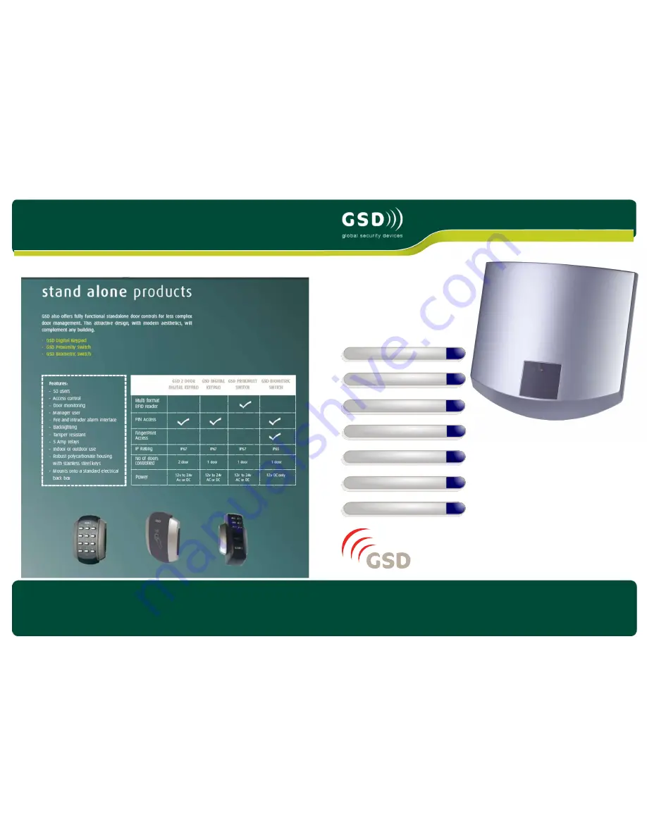
Other products from GSD

4

Installation Instructions

12

Network Diagrams

Wiring Diagrams

19

Fingerprint Enrollment

Operation Instructions

Global Security Devices Ltd: No.3 Broomhill Business Complex, Tallaght,

Dublin 24, Ireland, 

Phone

: +353 (1) 524 2691, 

Email

: [email protected]

www.globalsecurity.ie

YOUR SECURITY IS OUR PRIORITY

Summary of Contents for Wi-Corporate Controller

Page 1: ...roducts from GSD 4 Installation Instructions 12 Network Diagrams Wiring Diagrams 19 Fingerprint Enrollment Operation Instructions Global Security Devices Ltd No 3 Broomhill Business Complex Tallaght Dublin 24 Ireland Phone 353 1 524 2691 Email info globalsecurity ie www globalsecurity ie YOUR SECURITY IS OUR PRIORITY ...

Page 2: ...rts Wireless RS485 Networks Automatic Backup Facility Database Encryption 30000 individual usergroups are available 20 30000 128 128 128 Yes Yes Unlimited CCTV Lift control Yes Yes Yes Installation Steps Step Description Page 1 Install the Controller using the Installation Diagrams 4 5 2 Wire the Controller using the Wiring Diagrams 8 3 Install and wire each Door Control Refer to the Door Control ...

Page 3: ...r pull out on right and slide left to remove cover pull forward on right and slide left mount with 4 x 1 5 inch No 8 Security Type screws rear tamper switch cable entry cable entry cable entry cable entry spare cap access to rear void for wiring spirit level mains pcb mount hole mount hole mount hole 4 Installation Diagrams 5 Installation Diagrams ...

Page 4: ...ommunication range depends on building shape and construction methods used 7 System Overview Note If using a single Controller an RS232 cable may be used Max cable length 10 meters RS485 Connection to Door Controls Door Control 1 Door Control 2 Door Control 3 Door Control 4 20 RS485 Network to Door Controls Max Cable Length 1 4 km Daisy Chain Configuration Only Controller 1 Controller 2 3 Note If ...

Page 5: ...a suitably qualified person only Cable Tie retaining clips Main Input Cable 230VAC Neutral Earth Live Remove Battery Tab Pull 9 Network Diagrams for Single Controller A B 0V TX RX A B 0V Door Network PC Network Connect DB9 cable to serial port on PC Maximum cable length 10 meters Direct Connect All Dip Switches OFF PC Direct DB9 Female Serial Cable PC Direct Connection can be used when using ONLY ...

Page 6: ... All OFF Address 1 Set SW1 ON Address 2 Set SW2 ON Note Address 3 Set SW3 ON only The Controller Address is set by configuring the Dip switches as shown below Configuring GSD Controller Communications Step Description 1 On the Controller Tab set the Connection Type to Serial 2 On the Settings tab in the communications section Select the Serial Port number from the drop down list connected to the C...

Page 7: ...ontroller e g 192 168 1 26 7 Make sure the controller is online and click on the Controller TCP IP Configuration button 8 Choose Static IP mode and enter the IP address Netmask and Default Gateway assigned by your network administrator Click Send new settings to Controller The Controller will now go offline as the new IP Address settings are applied 9 Connect the PC and Controller to your LAN and ...

Page 8: ...icon will change colour to show that the Controller is on line F Go to the Current Events tab and verify the log messages indicate the controller is on line 15 Operation Instructions Phase 2 Configuring the GSD Controller Step Description 1 Open the Doors tab in the main menu to add the required number of new doors to be part of this network One door will already be added by default Click on the b...

Page 9: ...complete 17 Operation Instructions Phase 3 Enrolling Door Controls Note For Wired 485 Door Controls right click on the Controller on the right hand side of the application and select Manually Assign Address from the drop down menu Once all new Door Controls are found by the Controller they will all beep with the number of the next available address door position on the Controller e g if door 2 is ...

Page 10: ...to inactive then access will be denied for all cards and PINs on that Door Control Example To Enable PIN codes only on a Wi PIN Prox Set the Timed Action Card or PIN to Inactive and set the Timed Action PIN Only to All day Every Day This will grant access for PIN codes and deny access for cards and fobs Phase 4 Configuring Users Step Description 1 Enable a User by ticking the Enabled box for each ...

Page 11: ...All available Doors window and drag it to the Doors in Current Door Group to add it to the Door Group Repeat for adding each door Step Description After all users access levels and door control settings have been finalised a full download to the controller should be carried out 1 Go to the Settings tab and click on Download Configuration A pop up window will appear tracking the status of the downl...

Page 12: ...Note The System does not store the finger print It uses an algorithm to generate a binary representation using sample points from the fingerprint It uses this information to then validate each users fingerprint Incorrect Finger Placement 23 Finger Placement Wi BIO Poor Quality Image Note Poor Quality image No Fingerprint core on sensor window This can result in poor template quality that can lead ...

Page 13: ...Correct Finger Placement 24 Finger Placement Wi BIO Incorrect Finger Placement 25 Finger Placement Wi BIO ...

Page 14: ... 14 15 16 17 18 19 20 1 2 3 4 5 6 7 8 9 10 Ctrl Door No Door Type Door Location Name Walk Test 1 2 11 12 13 14 15 16 17 18 19 20 1 2 3 4 5 6 7 8 9 10 11 12 13 14 15 16 17 18 19 20 Ctrl Door No Door Type Door Location Name Walk Test 2 3 Installation Records ...

Reviews: