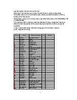
specified parts shown in the parts list.
*Warning: This product uses a laser diode. Refer to caution statements.
*Capacity values are in microfarads (uF) unless specified otherwise, P=Pico-
farads (pF) F=Farads (F)
*Resistance values are in ohms, unless specified otherwise, 1K=1,000 (OHM), 1M
=1,000K (OHM)
*The marking <RTL> indicates that the Retention Time is limited for this item.
After the discontinuation of this assembly in production, it will no longer be
available.
*"<IA>" mark in Remarks indicates languages of instruction manual.
[<IA>: English/ Chinese]
Ref. No.
Part No.
Part Name & Description
Pcs
Remarks
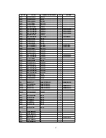
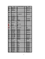
1
RDG0477
INTERMEDIATE GEAR
1
2
RHD14078
SCREW
1
3
RHW11011
WASHER
1
4
RMC0392-2
HOLDER SPRING
1
5
RXK0375
TRAVERSE UNIT
1
5-1
BRL1A1CWB
TRAVERSE MOTOR
1
5-2
RHD14074
SCREW
1
5-3
RJC99038
RECHARGE.BATT.TERMINAL(-)
1
5-4
RMX0156-1
STOPPER RUBBER
1
5-5
XQN14+B2FC
SCREW
1
6
RAF2000A-4M
OPTICAL PICKUP
1
7
RXJ0025
DRIVE SHAFT
1
8
RHD14067
SCREW
5
9
RJC99039-1
RECHARGE.BATT.TE)
1
10
RJR0195-2
BATTERY SHAFT
1
11
RGK1448-K
INTERMEDIATE CABINET
1
12
RHQ0083-S
SCREW
6
13
RXQ0829
LINK UNIT(R)
1
14
RXQ0830
LINK UNIT(L)
1
14-1
RGU2040-S
EJECT KNOB
1
15
RYF0612-S
DISC COVER
1
16
RYK1157-K
SIDE CABINET ASS’Y
1
17
RYK1156A-S
CABINET ASS’Y
1
17-1
RGU2041-S
OPERATION BUTTON
1
17-2
RGU2042-S
VOLUME BUTTON
1
17-3
RGV0296-S
HOLD KNOB
1
17-4
RMR1420-K
JACK PIECE
1
18
RHD14076-S
SCREW
6
19
RKK0156-S
BATTERY COVER
1
A1
K3ZZ00200041
EXTERNAL BATTERY CASE
1
A2
L0BAB0000162
STEREO EARPHONES
1
A3
L0EAAB000002
SPEAKER/BATTERY CHARGER
1
A4
N0JCBD000001
AC ADAPTOR
1
A5
N2QCBD000020
WIRED REMOTE CONTROLLER
1
A5-1
RFKY0010
REMOCON PANEL
1
61
Summary of Contents for SJ-MJ50GH
Page 5: ...3 Operating Instructions 4 Handling Precautions for MD Mechanism Optical 5 ...
Page 10: ... Check the P C B as shown below 10 ...
Page 11: ...5 2 Replacement for the disc cover ass y 11 ...
Page 12: ...5 3 Replacement for the side cabinet ass y Follow the Step 1 Step 3 of item 5 1 12 ...
Page 13: ...13 ...
Page 15: ...15 ...
Page 17: ...17 ...
Page 18: ...5 6 Replacement for the traverse motor Follow the Step 1 Step 3 of item 5 1 18 ...
Page 19: ...19 ...
Page 20: ...20 ...
Page 22: ...22 ...
Page 23: ...23 ...
Page 24: ...24 ...
Page 25: ...25 ...
Page 35: ...35 ...
Page 36: ...36 ...
Page 37: ...37 ...
Page 38: ...38 ...
Page 39: ...39 ...
Page 40: ...40 ...
Page 41: ...41 ...
Page 42: ...8 Schematic Diagram Notes 8 1 Type Illustration of IC s Transistors and Diodes 42 ...
Page 53: ...29 CHARGE O Recharge control output terminal 53 ...


