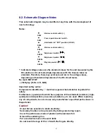
8.2. Schematic Diagram Notes
This schematic diagram may be modified at any time with the development of
new technology.
Notes:
S202
: Volume control switch (+)
S207
: Cover open/close det. switch
S208
: Hold switch in “OFF” position. (HOLD)
SX201
: Volume control switch (-)
SX203
: Skip/search switch (
)
SX204
: Skip/search switch (
)
SX206
: Play/stop switch (
)
-
Indicated voltage values are the standard values for the unit measured by the
DC electronic circuit tester (high-impedance) with the chassis taken as
standard. Therefore, there may exist some errors in the voltage values,
depending on theinternal impedance of the DC circuit tester.
No mark: MD STOP
( ): MD play [1kHz, L+R, 0dB]
Important safety notice:
Components identified by mark have special characteristics important for
safety.
Furthermore, special parts which have purpose of fire-retardant (resistors), high-
quality sound (capacitors), low-noise (resistors), etc. are used. When replacing
any of components, be sure to use only manufacture's specified parts shown in
theparts list.
Caution!
IC and LSI are sensitive to static electricity.
Secondary trouble can be prevented by taking care during repair.
Cover the parts boxes made of plastics with aluminum foil.
Ground the soldering iron.
Put a conductive mat on the work table.
Do not touch the legs of IC or LSI with the fingers directly.
43
Summary of Contents for SJ-MJ50GH
Page 5: ...3 Operating Instructions 4 Handling Precautions for MD Mechanism Optical 5 ...
Page 10: ... Check the P C B as shown below 10 ...
Page 11: ...5 2 Replacement for the disc cover ass y 11 ...
Page 12: ...5 3 Replacement for the side cabinet ass y Follow the Step 1 Step 3 of item 5 1 12 ...
Page 13: ...13 ...
Page 15: ...15 ...
Page 17: ...17 ...
Page 18: ...5 6 Replacement for the traverse motor Follow the Step 1 Step 3 of item 5 1 18 ...
Page 19: ...19 ...
Page 20: ...20 ...
Page 22: ...22 ...
Page 23: ...23 ...
Page 24: ...24 ...
Page 25: ...25 ...
Page 35: ...35 ...
Page 36: ...36 ...
Page 37: ...37 ...
Page 38: ...38 ...
Page 39: ...39 ...
Page 40: ...40 ...
Page 41: ...41 ...
Page 42: ...8 Schematic Diagram Notes 8 1 Type Illustration of IC s Transistors and Diodes 42 ...
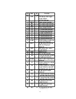
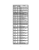
Page 53: ...29 CHARGE O Recharge control output terminal 53 ...

