


-
Laser diode in the optical pickup may be destroyed by the static electricity
generated in your clothes or body. Be especially careful with the static
electricity.
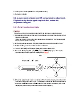
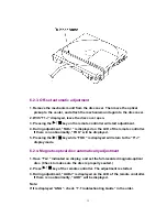
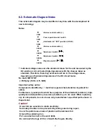
6.2.2.2. Adjustment Procedure
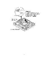
1. Uncover the laser power meter. (as shown in
Fig. 6
)
Fig. 6
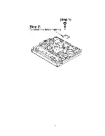
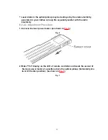
2. Make “T0J” display on the LCD of remote controller and locate the sensor of
the laser power meter at a position above the optical pickup (horizontally at a
level of the disc position). (as shown in
Fig. 7
)
Fig. 7
29
Summary of Contents for SJ-MJ50GH
Page 5: ...3 Operating Instructions 4 Handling Precautions for MD Mechanism Optical 5 ...
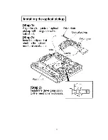
Page 10: ... Check the P C B as shown below 10 ...
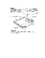
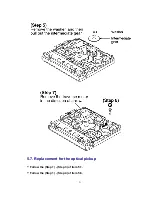
Page 11: ...5 2 Replacement for the disc cover ass y 11 ...
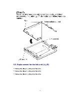
Page 12: ...5 3 Replacement for the side cabinet ass y Follow the Step 1 Step 3 of item 5 1 12 ...
Page 13: ...13 ...
Page 15: ...15 ...
Page 17: ...17 ...
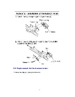
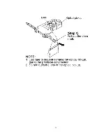
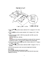
Page 18: ...5 6 Replacement for the traverse motor Follow the Step 1 Step 3 of item 5 1 18 ...
Page 19: ...19 ...
Page 20: ...20 ...
Page 22: ...22 ...
Page 23: ...23 ...
Page 24: ...24 ...
Page 25: ...25 ...
Page 35: ...35 ...
Page 36: ...36 ...
Page 37: ...37 ...
Page 38: ...38 ...
Page 39: ...39 ...
Page 40: ...40 ...
Page 41: ...41 ...
Page 42: ...8 Schematic Diagram Notes 8 1 Type Illustration of IC s Transistors and Diodes 42 ...
Page 53: ...29 CHARGE O Recharge control output terminal 53 ...


