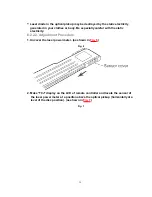
But if available is a MD cartridge type only, follow the procedure below.
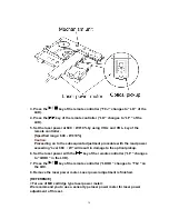
1. Disassemble the unit so that only the mechanism unit and the printed circuit
board are exposed. (as shown in
Fig. 8
)
2. Set the laser power meter cartridge. (as shown in
Fig. 8
)
3. Set the battery and attach and secure the battery cover with a rubber band.
(as shown in
Fig. 9
)
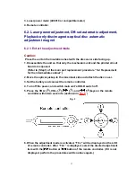
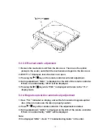
4. Follow the steps for “6.2.1. Enter the adjustment mode”. (Subsequent
procedures are the same as those for the sensor type.)
Fig. 8
Fig. 9
31
Summary of Contents for SJ-MJ50GH
Page 5: ...3 Operating Instructions 4 Handling Precautions for MD Mechanism Optical 5 ...
Page 10: ... Check the P C B as shown below 10 ...
Page 11: ...5 2 Replacement for the disc cover ass y 11 ...
Page 12: ...5 3 Replacement for the side cabinet ass y Follow the Step 1 Step 3 of item 5 1 12 ...
Page 13: ...13 ...
Page 15: ...15 ...
Page 17: ...17 ...
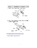
Page 18: ...5 6 Replacement for the traverse motor Follow the Step 1 Step 3 of item 5 1 18 ...
Page 19: ...19 ...
Page 20: ...20 ...
Page 22: ...22 ...
Page 23: ...23 ...
Page 24: ...24 ...
Page 25: ...25 ...
Page 35: ...35 ...
Page 36: ...36 ...
Page 37: ...37 ...
Page 38: ...38 ...
Page 39: ...39 ...
Page 40: ...40 ...
Page 41: ...41 ...
Page 42: ...8 Schematic Diagram Notes 8 1 Type Illustration of IC s Transistors and Diodes 42 ...
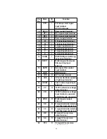
Page 53: ...29 CHARGE O Recharge control output terminal 53 ...


