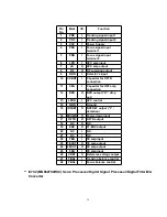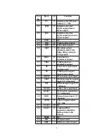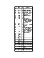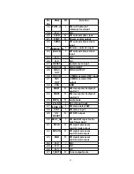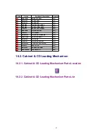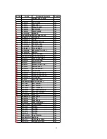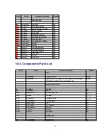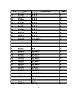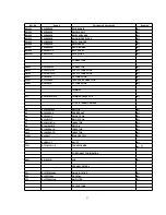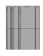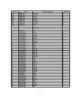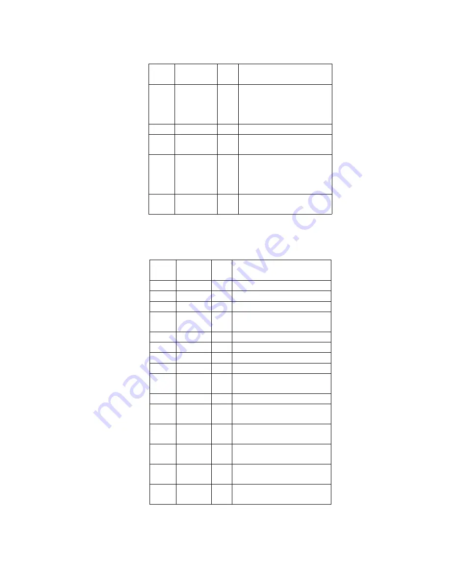
Pin
No.
Mark
I/O
Function
76
RSEL
I
RF signal polarity
assignment input (at “H”
level: RSEL = “H”) (at “L”
level: RSEL = “L”)
77
IOVDD
I
5V Supply
78
PSEL
I
Test terminal (connected
to Gnd)
79
MSEL
I
SMCK oscillating
frequency designation
input (“L”: 4.2336MHz,
“H”: 8.4672MHz)
80
SSEL
I
SUBQ output mode select
(“H”: Q-code buffer mode)
-
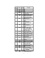
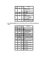
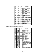
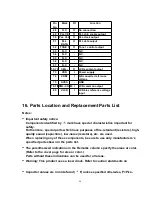
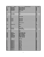
IC703 (AN8739SBE2) Focus Coil/Tracking Coil/Traverse Motor/Spindle Motor
Driver
Pin
No.
Mark
I/O
Function
1
/RST
-
N.C.
2
NC
-
N.C.
3
IN2
I
Motor Drive (2) input
4
PC2
I
Turn table motor drive
signal (“L”:ON)
5
NC
-
N.C.
6
IN1
I
Motor Driver (1) input
7
NC
I
N.C.
8
PVCC1
I
Power supply (1) for driver
9
PGND1
-
Ground connection (1) for
driver
10
NC
-
N.C.
11
D1-
O
Motor driver (1) reverse-
action output
12
D1+
O
Motor driver (1) forward-
action output
13
D2-
O
Motor driver (2) reverse-
action output
14
D2+
O
Motor driver (2) forward-
action output
15
D3-
O
Motor driver (3) reverse-
action output
41
Summary of Contents for RXD10 - RADIO CASSETTE W/CD
Page 6: ...6 ...
Page 8: ...6 Controls 8 ...
Page 9: ...9 ...
Page 13: ...13 ...
Page 14: ...14 ...
Page 15: ...15 ...
Page 17: ...8 1 2 Checking for CD Servo P C B 17 ...
Page 18: ...Step 9 Remove the FFC wire from CN702 18 ...
Page 19: ...8 2 Main Component Replacement Procedures 8 2 1 Replacement of the Traverse Deck 19 ...
Page 21: ...Note Insert a short pin into the flexible cable for traverse unit 21 ...
Page 22: ...Step 4 Remove the flexible cable CN701 22 ...
Page 26: ...26 ...
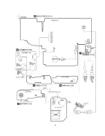
Page 27: ...10 Printed Circuit Board 11 Wiring Connection Diagram 27 ...
Page 28: ...28 ...
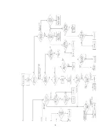
Page 29: ...12 Troubleshooting Guide 29 ...
Page 30: ...30 ...

