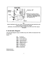
Note :
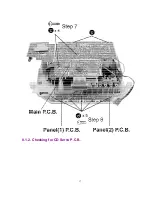
Before installing the CD servo P.C.B., move the optical pickup towards the outer
edge from the marking (black triangle).
[Otherwise, the detect switch (S701) mounted on the CD servo P.C.B. may be
damaged.]
9. Schematic Diagram
(All schematic diagrams may be modified at any time with the development of new
technology.)
Notes:
S701
Rest Switch
SW302
Function Switch
SW601
Reverse Skip Switch
SW602
Forward Skip Switch
SW603
Play/Pause Switch
SW604
FM Mode/Clear Switch
SW605
Play/Mode Switch
SW606
Memory Switch
SW607
Tone/XBS Switch
SW802
CD Leaf Switch
SW1001 Record Switch
Battery Current:
Volume minimum :
24
Summary of Contents for RXD10 - RADIO CASSETTE W/CD
Page 6: ...6 ...
Page 8: ...6 Controls 8 ...
Page 9: ...9 ...
Page 13: ...13 ...
Page 14: ...14 ...
Page 15: ...15 ...
Page 17: ...8 1 2 Checking for CD Servo P C B 17 ...
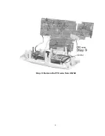
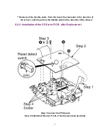
Page 18: ...Step 9 Remove the FFC wire from CN702 18 ...
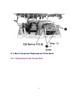
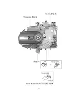
Page 19: ...8 2 Main Component Replacement Procedures 8 2 1 Replacement of the Traverse Deck 19 ...
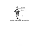
Page 21: ...Note Insert a short pin into the flexible cable for traverse unit 21 ...
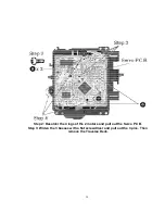
Page 22: ...Step 4 Remove the flexible cable CN701 22 ...
Page 26: ...26 ...
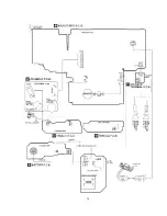
Page 27: ...10 Printed Circuit Board 11 Wiring Connection Diagram 27 ...
Page 28: ...28 ...
Page 29: ...12 Troubleshooting Guide 29 ...
Page 30: ...30 ...

