


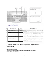


1. This section describes procedures for checking the operation of the major
printed circuit boards and replacing the main components.
2. For reassembly after operation checks or replacement, reverse the respective
procedures.
Special reassembly procedures are described only when required.
3. Select items from the following index when checks or replacement are required.
4. Refer the Parts No. on the page of “Main component Replacement Procedures”, if
necessary.
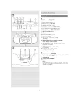
Content
-
Disassembly Procedure for each major P.C.B.
1. ing for the Main, Panel1, Panel2 & Speaker Terminal P.C.B
........................................................................ P.g. 7 ~ 8
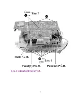
2. Checking for the CD Servo P.C.B
..................................................................................................................................
P.g. 8
-
Main Component Replacement Procedures
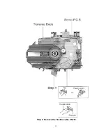
1. Replacement of the Traverse Deck
..............................................................................................................................
P.g.9
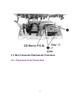
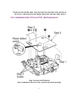
2. Installation of the CD Servo P.C.B. after Replacement
................................................................................................ P.g.10
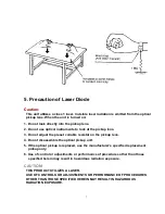
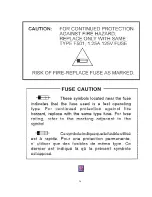
Warning:
This product uses a laser diode. Refer to
.
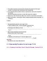
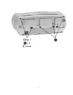
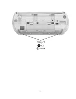
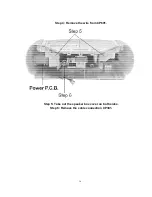
8.1. Disassembly Procedure for each major P.C.B.
8.1.1. Checking for the Main, Panel1, Panel2 & Speaker Terminal P.C.B
12
Summary of Contents for RXD10 - RADIO CASSETTE W/CD
Page 6: ...6 ...
Page 8: ...6 Controls 8 ...
Page 9: ...9 ...
Page 13: ...13 ...
Page 14: ...14 ...
Page 15: ...15 ...
Page 17: ...8 1 2 Checking for CD Servo P C B 17 ...
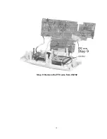
Page 18: ...Step 9 Remove the FFC wire from CN702 18 ...
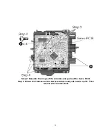
Page 19: ...8 2 Main Component Replacement Procedures 8 2 1 Replacement of the Traverse Deck 19 ...
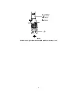
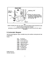
Page 21: ...Note Insert a short pin into the flexible cable for traverse unit 21 ...
Page 22: ...Step 4 Remove the flexible cable CN701 22 ...
Page 26: ...26 ...
Page 27: ...10 Printed Circuit Board 11 Wiring Connection Diagram 27 ...
Page 28: ...28 ...
Page 29: ...12 Troubleshooting Guide 29 ...
Page 30: ...30 ...


