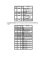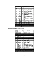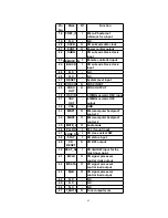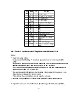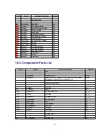
Pin
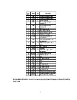
No.
Mark
I/O
Function
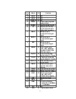
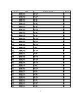
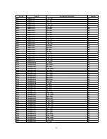
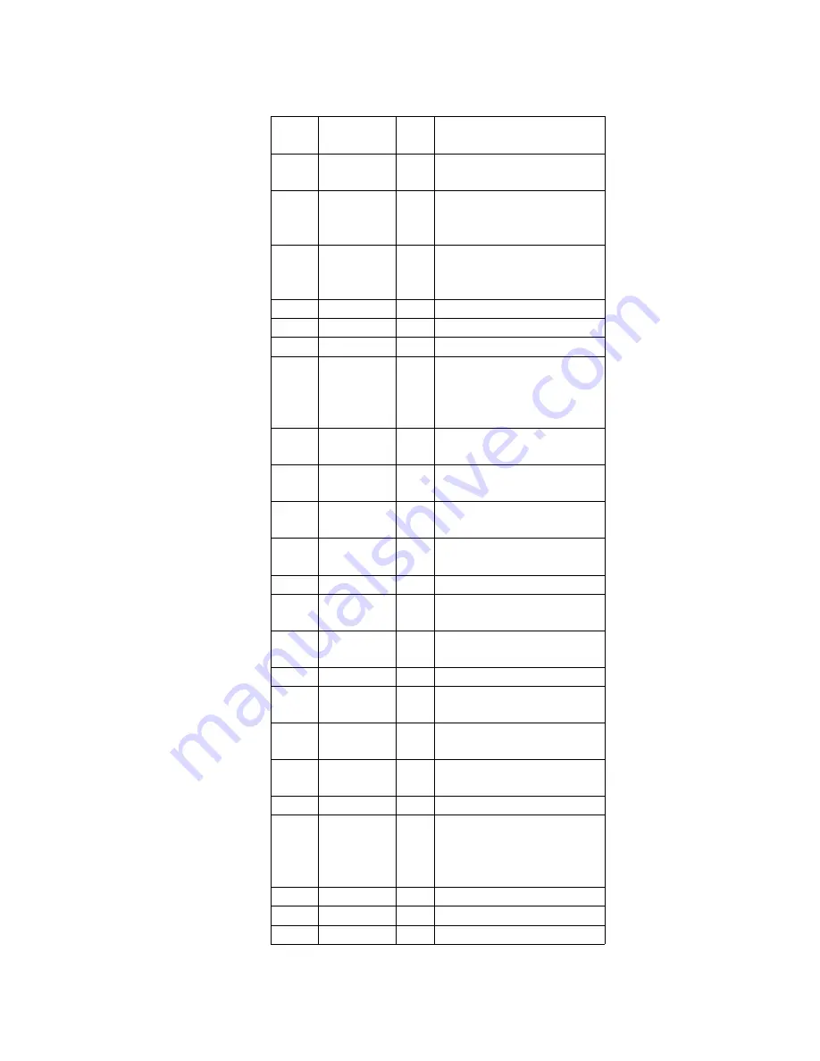
23
PC
O
Spindle motor ON signal
output (“L”: ON)
24
ECM
O
Spindle motor drive
signal output (forced
mode output)
25
ECS
O
Spindle motor drive
signal output (servo error
signal output)
26
KICK
O
N.C.
27
TRD
O
Tracking drive output
28
FOD
O
Focus drive output
29
VREF
I
D/A (drive) output
(TVD,ECS, TRD, FOD,
FBAL, TBAL) reference
voltage input
30
FBAL
O
Focus balance
adjustment output
31
TBAL
O
Tracking balance
adjustment output
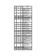
32
FE
I
Focus error signal input
(analog input)
33
TE
I
Tracking error signal
input (analog input)
34
RFENV
I
RF envelope signal input
35
VDET
I
Vibration detection signal
input (“H”: detection)
36
OFT
I
Off-track signal input (“H”
: off track)
37
TRCRS
I
Track cross signal input
38
/RFDET
I
RF detection signal input
(“L”: detection)
39
BDO
I
Dropout signal input (“H”:
Dropout)
40
LDON
O
Laser on signal output
(“H”: ON)
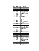
41
PLLF2
I/O
N.C.
42
DSLF2
O
Tracking Offset
alignment output/DSL
Balance Output (DA
Output)
43
WVEL
O
N.C.
44
ARF
I
RF signal input
45
IREF
I
Reference current input
39
Summary of Contents for RXD10 - RADIO CASSETTE W/CD
Page 6: ...6 ...
Page 8: ...6 Controls 8 ...
Page 9: ...9 ...
Page 13: ...13 ...
Page 14: ...14 ...
Page 15: ...15 ...
Page 17: ...8 1 2 Checking for CD Servo P C B 17 ...
Page 18: ...Step 9 Remove the FFC wire from CN702 18 ...
Page 19: ...8 2 Main Component Replacement Procedures 8 2 1 Replacement of the Traverse Deck 19 ...
Page 21: ...Note Insert a short pin into the flexible cable for traverse unit 21 ...
Page 22: ...Step 4 Remove the flexible cable CN701 22 ...
Page 26: ...26 ...
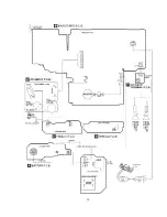
Page 27: ...10 Printed Circuit Board 11 Wiring Connection Diagram 27 ...
Page 28: ...28 ...
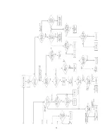
Page 29: ...12 Troubleshooting Guide 29 ...
Page 30: ...30 ...

