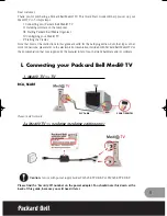
tube.
8. After servicing make the following leakage current checks to
prevent the customer from being exposed to shock hazards.
1.2. LEAKAGE CURRENT COLD CHECK
1. Unplug the AC cord and connect a jumper between the two
prongs on the plug.
2. For physically operated power switches, turn power on. Otherwise
skip step 2.
3. Measure the resistance value, with an ohmmeter, between the
jumpered AC plug and each exposed metallic cabinet part on the
receiver, such as screwheads, connectors, etc. When the exposed
metallic part has a return path to the chassis, the readingshould
be between 1 M and 12 M . When the exposed metal does not
have a return path to the chassis, the reading must be infinity.
1.3. LEAKAGE CURRENT HOT CHECK
1. Plug the AC cord directly into the AC outlet.
Do not use a isolation transformer for this check.
2. Connect a 1.5 k , 10 W resistor, in parallel with a 0.15 F
capacitor, between each exposed metallic part on the set and a
good earth ground, as shown in Figure 1.
3. Use an AC voltmeter, with 1 k /V or more sensitivity, to measure
the potential across the resistor.
4. Check each exposed metallic part, and measure the voltage at
each point.
5. Reverse the AC plug in the AC outlet and repeat each of the above
measurements.
6. The potential at any point should not exceed 0.75 V RMS.
A leakage current tester (Simpson Model 229 equivalent) may be
used to make the hot checks. Leakage current must not exceed 1/
2 mA. In case a measurement is outside of the limits specified,
there is a possibility of shock hazard, and thereceiver should be
repaired and rechecked before it is returned to the customer.
Figure 1
4
Summary of Contents for PVDM2092 - MONITOR/DVD COMBO
Page 1: ...ORDER NO MKE0207607C1 B22 TV DVD VCR Combination PV DM2092 PV DM2092 K SPECIFICATIONS 1...
Page 10: ...Fig 1 4 Fig 1 5 10...
Page 27: ...CAUTION Disconnect AC plug before disassembly Fig D1 Fig D2 27...
Page 28: ...Fig D3 28...
Page 29: ...6 1 1 1 Notes in chart 1 Removal of VCR DVD Ass y Fig D4 29...
Page 33: ...6 2 3 EJECT Position Confirmation Fig J1 2 33...
Page 34: ...6 2 4 Full Erase Head and Cylinder Unit Fig J2 34...
Page 76: ...76...
Page 79: ...11 2 MECHANISM BOTTOM SECTION 79...
Page 80: ...11 3 CASSETTE UP COMPARTMENT SECTION 80...
Page 81: ...11 4 CHASSIS FRAME SECTION 1 81...
Page 82: ...11 5 CHASSIS FRAME SECTION 2 82...
Page 83: ...11 6 CHASSIS FRAME SECTION 3 83...
Page 84: ...11 7 PACKING PARTS AND ACCESSORIES SECTION 84...