1
(FROM IC6001(49))
DVD POWER ON(H)
T1001
IC1001
POWER SUPPLY C.B.A.
T1301
12
D1304
3
1
RECTIFIER
D1305
SMOOTHING
C1314
PR1301
+27V
9
(SWITCHING)
Q1302
5
D1302
D1301
F1301
1.6A 125V/250V
D1303
SWITCHING
CONTROL
Q1301
IC1301
IC1302
2
3
1
3
2
SHUNT
REG.
4
1
AC
CORD
TP891
+130V
REGULATOR
IC801
TP892
(TO T551 (9))
+130V
TV MAIN C.B.A.
RL801
Q801
SW+12V
(FROM IC6001(44))
TV POWER ON (H)
FULL-WAVE
RECTIFIER
D801 D804
L803
LINE
FILTER
LINE
FILTER
L801
LINE
FILTER
L1301
F801
6.3A 125V/250V
P801
3
P801
1
SW+12V
Q802
3
4
5
P1301
1
P1302
1
FULL-WAVE
RECTIFIER
6
P806
1
P805
1
P803
1
P802
1
9
10
12
13
NOT USED
J811
SW+30V(TUNER)
UNSW+14V
(FROM IC6001(28))
POWER ON(L)
UNSW+5V
(VIDEO)
UNSW+5V
(SYS-CTL)
SW+5V(TUNER)
Q1053
SW+12V
SW-5.1V
Q1051
Q1052
Q1070,Q1071
ERROR
VOLTAGE
DET
-5.1V
REGULATOR
7
8
11
J1080
Q1080
Q1081
NOT USED
PR1001
PR1070
PR1071
D1005
SMOOTHING
C1011
SMOOTHING
C1012,1013
D1015
OVER VOLTAGE
PROTECTOR
RECTIFIER
D1006
RECTIFIER
D1008
SMOOTHING
C1016,C1017
SMOOTHING
C1071
RECTIFIER
D1071
RECTIFIER
14
1
2
IC1002
SHUNT
REG.
1
3
2
(SWITCHING)
Q1001
SWITCHING
CONTROL
Q1002
D1002
D1003
D1017
D1016
D1001
FULL-WAVE
RECTIFIER
4
3
L1001
F1001
3A 125V/250V
SWITCHING
CONTROL
D1501
IC1501
D1502
D1503
D1506
D1505
4
5
1
2
LINE
FILTER
FULL-WAVE
RECTIFIER
P1001
1
P1001
2
T1501
IC1502
2
4
D1507
D1504
9
11
10
7
6
4
3
13
13
12
6
5
2
3
14
13
RECTIFIER
RECTIFIER
SMOOTHING
SMOOTHING
D1508
C1510,C1513
C1511,C1515
D1509
IC1503
1
3
2
SHUNT
REG.
1
2
PR1502
PR1501
Q1504
Q1503
ERROR
VOLTAGE
DET
Q1502
Q1501
Q1506
Q1505
+30V
P1503
P1504
P1505
P1506
CONNECTOR
CABLE
YELLOW
WHITE
RED
BLACK
SW+5V(D)
SW+5V(A)
TO DVD
UNIT
P1501
6,7
P1501
8,9
DRIVE
+12V
DRIVE+5V
PR1002
50 V
2 µs
V1
309.0 Vp-p
B
50 V
2 µs
V1
309.0 Vp-p
C
20 V
2 µs
V1
38.0 Vp-p
D
10 V
2 µs
V1
33.0 Vp-p
E
0.1 V
2 µs
V1
0.26 Vp-p
A
E
C
D
B
A
50 V
2 µs
V1
282.2 Vp-p
V1
90.5 Vp-p
50 V
2 µs
50 V
1 µs
V1 275.5 Vp-p
20 V
1 µs
V1
61.6 Vp-p
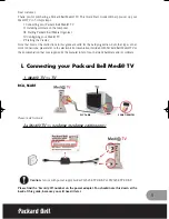
POWER SUPPLY BLOCK DIAGRAM
PV-DM2092/PV-DM2092-K POWER SUPPLY BLOCK DIAGRAM
Summary of Contents for PVDM2092 - MONITOR/DVD COMBO
Page 1: ...ORDER NO MKE0207607C1 B22 TV DVD VCR Combination PV DM2092 PV DM2092 K SPECIFICATIONS 1...
Page 10: ...Fig 1 4 Fig 1 5 10...
Page 27: ...CAUTION Disconnect AC plug before disassembly Fig D1 Fig D2 27...
Page 28: ...Fig D3 28...
Page 29: ...6 1 1 1 Notes in chart 1 Removal of VCR DVD Ass y Fig D4 29...
Page 33: ...6 2 3 EJECT Position Confirmation Fig J1 2 33...
Page 34: ...6 2 4 Full Erase Head and Cylinder Unit Fig J2 34...
Page 76: ...76...
Page 79: ...11 2 MECHANISM BOTTOM SECTION 79...
Page 80: ...11 3 CASSETTE UP COMPARTMENT SECTION 80...
Page 81: ...11 4 CHASSIS FRAME SECTION 1 81...
Page 82: ...11 5 CHASSIS FRAME SECTION 2 82...
Page 83: ...11 6 CHASSIS FRAME SECTION 3 83...
Page 84: ...11 7 PACKING PARTS AND ACCESSORIES SECTION 84...