


Chapter 4
Settings — [ADVANCED MENU] menu
86 - ENGLISH
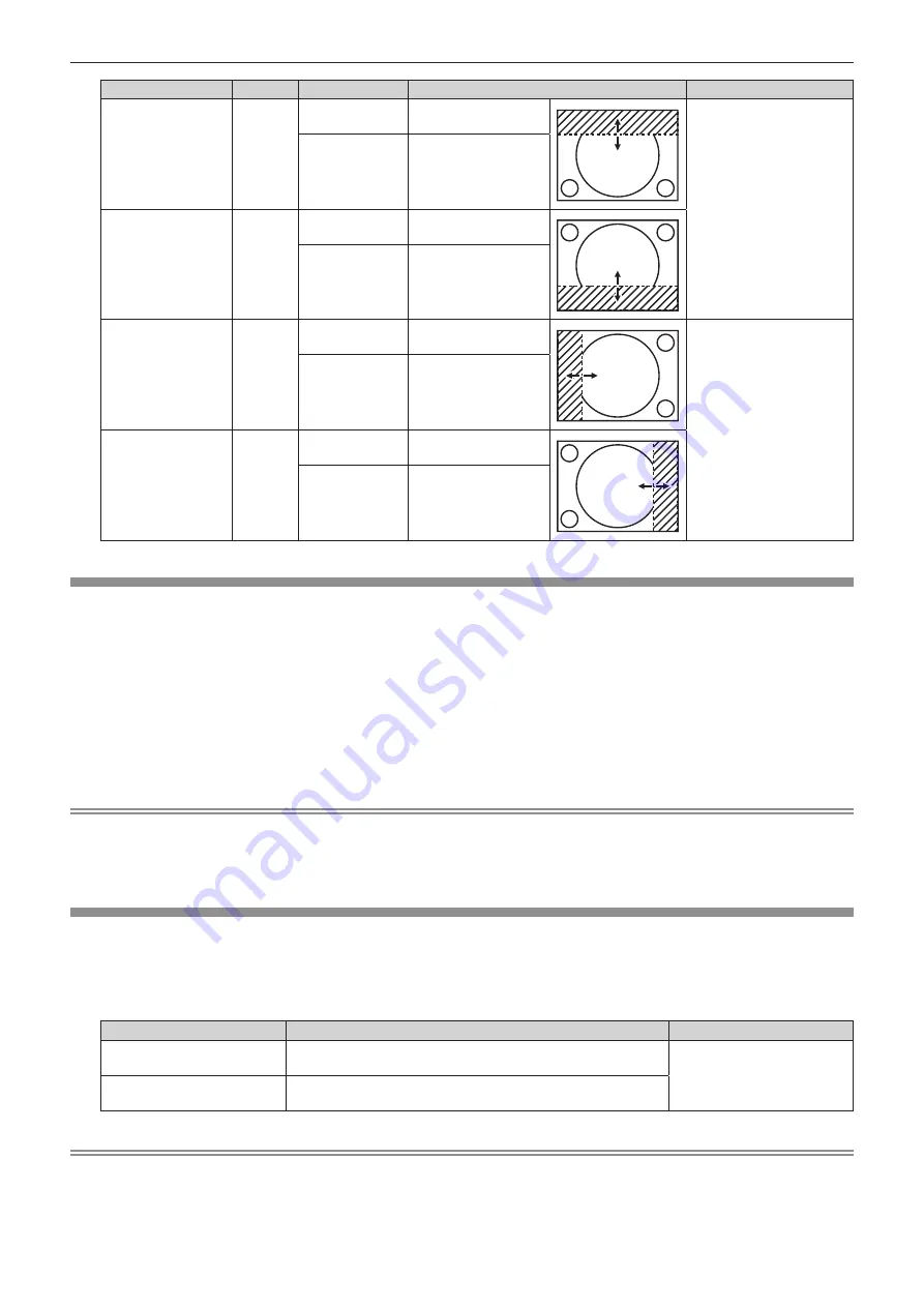
Blanking correction
Item
Operation
Adjustment
Range of adjustment
Top of the screen
[UPPER]
Press
q
.
The blanking zone
moves upward.
PT-RZ670: Top to bottom
0 - 599
PT-RW630: Top to bottom
0 - 399
Press
w
.
The blanking zone
moves downward.
Bottom of the
screen
[LOWER]
Press
w
.
The blanking zone
moves upward.
Press
q
.
The blanking zone
moves downward.
Left side of the
screen
[LEFT]
Press
w
.
The blanking zone
moves to the right.
PT-RZ670: Left to right
0 - 959
PT-RW630: Left to right
0 - 639
Press
q
.
The blanking zone
moves to the left.
Right side of the
screen
[RIGHT]
Press
q
.
The blanking zone
moves to the right.
Press
w
.
The blanking zone
moves to the left.
[INPUT RESOLUTION]
You can adjust to achieve an optimal image when there is a flickering image or smeared outlines.
1) Press
as
to select [INPUT RESOLUTION].
2) Press the <ENTER> button.
f
The
[INPUT RESOLUTION]
screen is displayed.
3) Press
as
to select [TOTAL DOTS], [DISPLAY DOTS], [TOTAL LINES], or [DISPLAY LINES], and press
qw
to adjust each item.
f
Values corresponding to the signal being input are displayed automatically for each item. Increase or decrease the displayed values
and adjust to the optimal point viewing the screen when there are vertical stripes or sections are missing from the screen.
Note
f
Previously mentioned vertical banding will not occur with all white signal input.
f
The image may be disrupted while performing the adjustment, but it is not a malfunction.
f
[INPUT RESOLUTION] can be adjusted only when an RGB signal is input to the <RGB 1 IN> terminal or the <RGB 2 IN> terminal.
f
Some signals may not be adjusted.
[CLAMP POSITION]
You can adjust the optimal point when the black part of the image is blunt or it has turned green.
1) Press
as
to select [CLAMP POSITION].
2)
Press
qw
to adjust.
Status
Rough guide for optimal value
Range of adjustment
The black part is blunt.
The point where bluntness of the black part improves the most is
the optimal value.
1 - 255
The black part is green.
The point where the green part becomes black, and the bluntness
has improved is the optimal value.
Note
f
[CLAMP POSITION] can be adjusted only when a signal is input to the <RGB 1 IN> terminal or the <RGB 2 IN> terminal.
f
Some signals may not be adjusted.


