background image

Read this first!

ENGLISH - 9

Important


Information

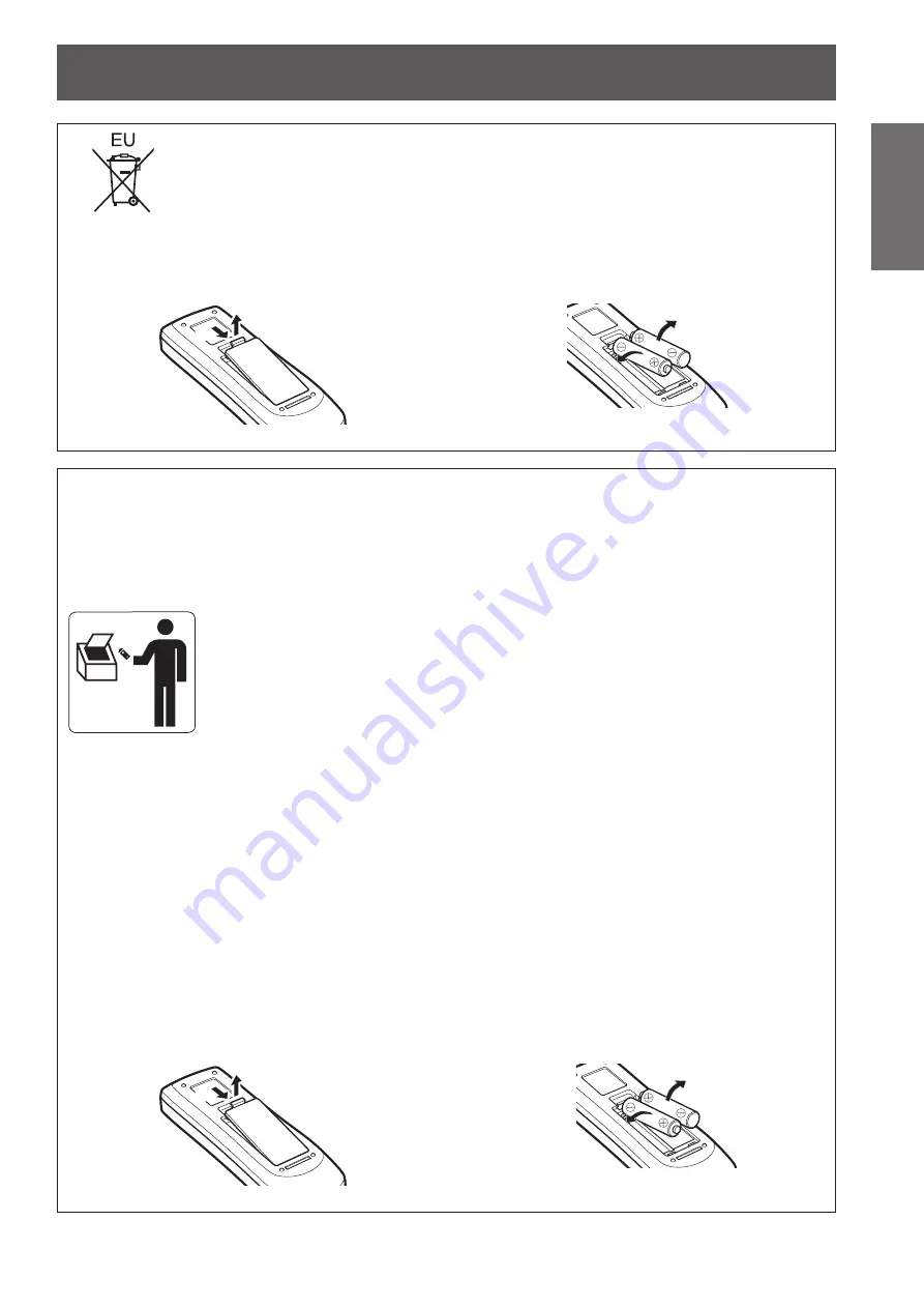
To remove the battery

Remote Control Battery
1. Press the guide and lift the cover.

(ii)

(i)

2. Remove the batteries.

Brazil Only

Brasil Apenas

„

Manuseio de baterias usadas

BRASIL

Após o uso, as pilhas e /ou baterias poderão 

ser entregues ao estabelecimento comercial 

ou rede de assistência técnica autorizada.

Cobrir os terminais positivo (+) e negativo (-) com uma fita isolante adesiva, antes de depositar numa caixa 

destinada para o recolhimento. O contato entre partes metálicas pode causar vazamentos, gerar calor, romper 

a blindagem e produzir fogo.

Não desmonte, não remova o invólucro, nem amasse a bateria. O gás liberado pela bateria pode irritar a 

garganta, danificar o lacre do invólucro ou o vazamento provocar calor, ruptura da blindagem e produzir fogo 

devido ao curto circuito dos terminais.

Não incinere nem aqueça as baterias, elas não podem ficar expostas a temperaturas superiores a 100 °C 

(212 °F). O gás liberado pela bateria pode irritar a garganta,

danificar o lacre do invólucro ou o vazamento provocar calor, ruptura da blindagem e produzir fogo devido ao 

curto circuito dos terminais provocado internamente.

Evite o contato com o liquido que vazar das baterias. Caso isto ocorra, lave bem a parte afetada com bastante 

água. Caso haja irritação, consulte um médico.

„

Remoção das baterias

1. Pressione a guia e levante a tampa.

(ii)

(i)

2. Remova as baterias.

Summary of Contents for PT-EX12KU

Page 1: ...product Before operating this product please read the instructions carefully and save this manual for future use Before using your projector be sure to read Read this first pages 2 to 10 For informat...

Page 2: ...ielded interface cables when connecting to computer or peripheral device If you use serial port to connect PC for external control of projector you must use optional RS 232C serial interface cable wit...

Page 3: ...ronment This equipment generates uses and can radiate radio frequency energy and if not installed and used in accordance with the instruction manual may cause harmful interference to radio communicati...

Page 4: ...severe electrical shock if the cut off plug is inserted into any 13 amp socket If a new plug is to be fitted please observe the wiring code as shown below If in any doubt please consult a qualified e...

Page 5: ...all outlets which are coming loose from the wall Do not use anything other than the provided power cord Failure to observe this will result in fire or electric shocks Clean the power plug regularly to...

Page 6: ...djustment and repair work please contact an Authorized Service Center Do not project an image with the lens cover attached Doing so can cause fire Do not allow metal objects flammable objects or liqui...

Page 7: ...s if necessary z z Battery fluid on your skin or clothing could result in skin inflammation or injury Rinse with clean water and seek medical advice immediately z z Battery fluid coming in contact wit...

Page 8: ...ure to observe this could cause injury When lifting or carrying the projector do not hold the lens hood and lens Doing so may damage the projector Always disconnect all cables before moving the projec...

Page 9: ...onte n o remova o inv lucro nem amasse a bateria O g s liberado pela bateria pode irritar a garganta danificar o lacre do inv lucro ou o vazamento provocar calor ruptura da blindagem e produzir fogo d...

Page 10: ...arks or registered trademarks of their respective holders Please note that the operating instructions do not include the and TM symbols Illustrations in these operating instructions Note that illustra...

Page 11: ...use lights for the control panel and connection terminals In addition you can choose one from nine types of optional lenses High reliability and maintainability Equipped with auto switchable two lamps...

Page 12: ...36 Connecting example Computers 36 Connecting example AV equipment 37 Tying up the cables using cable ties 38 Installing an input module optional 39 Installing an input module 39 List of compatible s...

Page 13: ...elect 70 Lamp power 70 Lamp interval 71 Edge blending 71 Color matching 72 Advanced color matching 73 HDMI setup 76 Logo 76 Fan control 77 Remote control 77 RC sensor 77 Power management 78 Direct on...

Page 14: ...z z Near the exhaust of an air conditioner or near lights studio lamps etc where there are large swings in temperature Operating environment page 115 Doing so may shorten the life of the lamp or resu...

Page 15: ...jector Security When using this product implement appropriate security measures to prevent the following z z Personal information being leaked via this product z z Unauthorized operation of this produ...

Page 16: ...garette smoke etc the replacement cycle for optical components such as the LCD panel and polarizer may reduce even when duration of use is less than a year For more information please consult your dea...

Page 17: ...001 1 set Lens attachment 1 T0HLA0045 1 set Lens hood strap T0SRZ0005 A 1 Accessory product name Quantity Cable tie 3 Power cord holder power cord cover T0STF0040 1 1 set Light shielding plate 1 1 T0C...

Page 18: ...Multi Projector Monitoring Control Software Windows This is software for monitoring and controlling multiple projectors connected via a LAN z zLogo Transfer Software Windows This is software to set th...

Page 19: ...et time when you press the P TIMER button page 49 14 KEYSTONE button Corrects the keystone effect page 48 15 INFO button Displays the state of signals during projection and current settings page 49 16...

Page 20: ...ly and horizontally but available operating distance may shorten z z If there are any obstacles between the remote control and the remote control sensor the remote control may not operate properly z z...

Page 21: ...ain power switch Turns off on the main power 13 AC input terminal Connect the supplied power cord page 41 14 Security slot This security slot is compatible with the Kensington security cables 15 Air i...

Page 22: ...lly and horizontally in the digital zoom mode or the real mode 7 AUTO PC ADJ button Automatically adjusts tracking total number of dots horizontal shift and vertical shift 8 LIGHT button Switches on o...

Page 23: ...is terminal is for use by service personnel 6 Serial input terminal SERIAL IN This input terminal is compatible with RS 232C and for externally controlling the projector by connecting the projector 7...

Page 24: ...control number will change to the new number z z To set the remote control number to 09 press 0 9 while holding down the MENU button Note z z The factory default setting is All All supports all remot...

Page 25: ...ching the lens For details refer to Accessories page 17 Caution When setting up the projector after attaching the lens be sure to fit the lens cover to the lens When carrying or holding the projector...

Page 26: ...front and rear of the lens install the lens attachment and secure with four screws supplied with the lens Focus lock screw Lens attachment Screwdriver supplied with the lens Locate the motor on the ri...

Page 27: ...plate Lower plate z z Make sure that the shape of the light shielding plate matches the lens z z Make sure that the attaching direction of the light shielding plate is correct and set them properly 7...

Page 28: ...Type SC A Lens lock lever T0STF0045 Attention z z In order to fix the attached lens securely be sure to mount the supplied lens lock lever fixing bracket 11 Insert the upper light shielding plate alo...

Page 29: ...plate interferes with lens operations set the light shielding plate again Attention z z Do not operate the projector with the light shielding plate removed Doing so may result in malfunction of the p...

Page 30: ...en proceed further adjustment i Turn the focus ring counterclockwise to loosen ii Rotate the lens to obtain the proper focus on outer area of the screen iii Turn the focus ring clockwise to tighten If...

Page 31: ...ns adjustment and improves the diagonal focus The corrected distance is determined by the thickness of the spacer to be inserted As a guide the corrected distance is approximately 30 mm by 0 1 mm in t...

Page 32: ...n the screw that was removed in Step 2 over the strap Lens hood strap CAUTION Do not pull the lens hood strap forcibly Doing so may deform this metal part and fail to attach the lens hood 5 Turn the l...

Page 33: ...8 0 13 3 31 0 22 2 45 5 31 1 22 6 17 5 7 62 300 11 2 8 6 4 9 12 5 9 5 9 4 7 3 16 2 12 4 21 6 16 0 37 2 26 6 54 6 37 2 27 1 20 9 8 89 350 13 1 10 1 5 8 14 6 11 1 11 0 8 5 18 9 14 5 25 3 18 7 43 4 31 0...

Page 34: ...cting from rear Using the translucent screen Setting on a desk floor and projecting forward Menu item Setting Ceiling On Rear On Menu item Setting Ceiling Off Rear Off Attention z z To get a high pict...

Page 35: ...justing adjustable feet The adjustable feet can be extended by turning it as shown in the figure It is retracted by turning it in the opposite direction This finely adjusts the height and tilt of the...

Page 36: ...O 9 FDEOH 9 0 FDEOH 6XE FDEOH 1 FDEOH 6HULDO FDEOH VWUDLJKW 7R 0 1 WHUPLQDO 7R 1 2 1 WHUPLQDO 7R 5 9 9 1 WHUPLQDO 7R 6 5 1 WHUPLQDO 7R VHULDO RXWSXW Note z z Use an HDMI High Speed cable that adheres...

Page 37: ...e may be distorted In such a case connect a time base corrector TBC between the projector and the device Note z z Use an HDMI High Speed cable that adheres to the HDMI standard Use of a cable that doe...

Page 38: ...he direction of arrow i 2 Pull the tab in the direction of arrow ii z z The loop of the cable tie will widen Attention z z Note that the following points when you use the cable tie Noises may occur in...

Page 39: ...tandard 720 60p 60 59 94 Hz 1 720 50p 50 Hz 1 V sync frequency 60 59 94 Hz 48 47 95 Hz and 24 23 98 Hz are automatically distinguished Note z z The preceding list shows the signal formats supported by...

Page 40: ...fies the types of signals compatible with the projector Screen display Resolution Scanning frequency Dot clock mode dots Horizontal kHz Vertical Hz frequency MHz D 480i 720 1 440 x 480 15 734 59 940 2...

Page 41: ...the power cord holder upward to allow insertion of the power cord 2 Insert the power cord cover in the direction of i and press it firmly in the direction of ii ii i 3 Connect the power cord to the AC...

Page 42: ...Off Flashing The projector is preparing to turn off the power After a short time the power will turn off in standby mode Note z z When the projector is preparing to turn off the power the power indic...

Page 43: ...hen Direct on page 78 of the Setting menu is set to On the power will be turned on as soon as you insert the power plug into the outlet or set the main power switch to the side z z When Display page 6...

Page 44: ...button on the remote control with the main power switch on the projector body turned on the projector continues to consume electricity For details on power consumption refer to Power consumption page...

Page 45: ...e Adjusting the position of the lens 1 Press the LENS SHIFT button on the remote control or the control panel z z Lens shift is displayed on the screen for four seconds Lens shift 2 While the display...

Page 46: ...s and Zoom are displayed press the FOCUS button and ZOOM button on the remote control or press on the control panel to adjust the focus and zoom Note z z When Display is set to Off the adjustment scre...

Page 47: ...ars when you press the SHUTTER button the button lock is enabled Check the Shutter setting from the Setting menu Using the freeze function You can temporarily freeze the projected image regardless of...

Page 48: ...ction display and the corner correction display Standard keystone effect correction Corrects the keystone effect vertically and horizontally 1 While Keystone is displayed press of the direction in whi...

Page 49: ...een menu will return to the factory default settings Displaying a timer for presentations When you press the P TIMER button on the remote control the projector displays either a count of the time elap...

Page 50: ...ENTER button and to change the settings or adjust the parameter values z z For some sub menus a further menu sub menu 2 containing advanced settings will be displayed To display sub menu 2 select a s...

Page 51: ...set and adjust the various items in the sub menu Input Sub menu item Factory default Page Input 1 RGB PC analog 54 Input 2 RGB 54 Input 3 Input 4 Note z z The signal displayed for Input 3 and Input 4...

Page 52: ...nced color Auto 63 Sharpness For computer input 0 For video input 15 63 Gamma 8 63 Noise reduction 1 On 63 Progressive 1 On 63 Reset 64 Store 64 1 Only displayed and selectable when video input is use...

Page 53: ...atching Off 72 HDMI setup Normal 76 Logo 76 Fan control Normal 77 Remote control All 77 RC sensor Both 77 Power management Off Timer 30 minutes 78 Direct on Off 78 Security 79 Projector ID All 80 Shut...

Page 54: ...SCART21 pin terminal is a video output terminal provided in video players sold mainly in Europe To view RGB output from this terminal on the projector connect the SCART21 pin terminal of the video pl...

Page 55: ...Store There is no input signal from the computer Check the connections Mode 1 Mode 10 Displays the mode registered with Store in PC adjust For video and S video input Auto The projector automatically...

Page 56: ...76i 1035i 1080i or 1080p have been selected using System in the Input menu z z With some computers and types of signal it may not be possible to project the images correctly Fine sync Adjusts the proj...

Page 57: ...3 While looking at the screen press to adjust the setting z z Press the ENTER button to return to the sub menu Display area H Adjusts the horizontal resolution 1 Press to select Display area H 2 Pres...

Page 58: ...enu 2 3 Press to select the mode to delete 4 Press the ENTER button 5 Select Yes and press the ENTER button z z The selected mode is deleted and the projector returns to the sub menu 2 z z Select No a...

Page 59: ...ted image to suit the environment in which you are using the projector Standard Resets the Image adjust menu items to the factory default settings Real In this mode intermediate settings are adjusted...

Page 60: ...r of images Brightness 1 Press to select Brightness 2 Press the ENTER button z z The adjustment screen is displayed 3 While looking at the screen press to adjust the setting Operation Adjustment Range...

Page 61: ...z Displays COLOR MANAGEMENT LIST z z You can check whether the registered color has been stored LIST Displays COLOR MANAGEMENT LIST COLOR M Cancels the adjustment and returns the cursor to the colorl...

Page 62: ...ss to select Red or Green or Blue 2 Press the ENTER button z z The adjustment screen is displayed 3 While looking at the screen press to adjust the setting Operation Adjustment Range Press Deepens red...

Page 63: ...oking at the screen press to adjust the setting Operation Adjustment Range Press Brightens the intermediate gradations 0 15 Press Darkens the intermediate gradations Noise reduction Reduces noise when...

Page 64: ...ess to select Store 2 Press the ENTER button z z The registered content of each mode is displayed in the sub menu 2 3 Press to select the mode to register z z Image 1 Image 10 4 Press the ENTER button...

Page 65: ...mage is horizontally wider than the panel the right and left edges will be cropped If vertically longer than the panel the top and bottom edges will be cropped 1 Press to select Zoom 2 Press the ENTER...

Page 66: ...z z Press the ENTER button to return to the sub menu Scale H Adjusts the horizontal scale Scale V Adjusts the vertical scale H V When adjusting the vertical and horizontal scale select On to link the...

Page 67: ...t menu the image move function of Digital zoom may not work correctly z z When VGA SVGA SXGA WXGA or UXGA is selected in System of the Input menu and the upward Keystone adjustment is at the maximum v...

Page 68: ...ly one of Standard and Corner correction Ceiling Sets the projection method in accordance with the installation status of the projector If the screen display is upside down select On z z This setting...

Page 69: ...of the on screen menu 1 Press to select Display 2 Press the ENTER button 3 Press to select an item and press the ENTER button Off The following screen displays appear z z Menu display z z Display of...

Page 70: ...ails as a result of a fault or reaching the end of its service life the lamp indicator LAMP 1 REPLACE LAMP 2 REPLACE on the front of the projector body An X mark will also appear as the lamp status at...

Page 71: ...to red when the setting value for the edge blending width is 1 or larger Note z z Even when the Edge blending setting screen is displayed if you press the ZOOM button the FOCUS button the LENS SHIFT...

Page 72: ...Press any button to return to the setting screen To reset a value during adjustment The setting returns to its value before adjustment 1 Press to select Reset 2 Press the ENTER button z z A screen fo...

Page 73: ...ed in Store 1 Press to select Reset 2 Press the ENTER button z z A screen for confirming whether to reset is displayed 3 Select Yes and press the ENTER button To register adjusted content you have cha...

Page 74: ...umber 0 9 buttons of the remote control Color x y L Red 0 000 1 000 0 000 1 000 0 000 1 000 Green 0 000 1 000 0 000 1 000 0 000 1 000 Blue 0 000 1 000 0 000 1 000 0 000 1 000 To check Target 1 Press t...

Page 75: ...alue during adjustment The setting returns to its value before adjustment The values of Measured and Target return to the standard value stored in Store 1 Press to select Reset 2 Press the ENTER butto...

Page 76: ...egistered by the user Default Displays in the factory default settings 1 Available when the image is registered z z Logo Transfer Software is required to register the image Logo PIN code lock Sets the...

Page 77: ...fan operation automatically Max Forces the fan to work at maximum capacity Then sound of the fan rotating will be louder than with Normal Remote control Allows simultaneous control or individual cont...

Page 78: ...sed During lamp cooling you cannot operate the projector When lamp cooling has finished the power will turn off Timer Sets times from 1 30 minutes Note z z The factory default setting is Off z z The p...

Page 79: ...ayed 2 Press or the number 0 9 buttons to enter the PIN code 3 Press to select Set 4 Press the ENTER button z z If the PIN code is accepted the projector returns to the sub menu 2 5 Press to switch th...

Page 80: ...the sub menu 2 Projector ID Sets the projector ID 1 to 64 for the RS 232C serial communication 1 Press to select Projector ID 2 Press the ENTER button 3 Press to switch the setting z z The factory def...

Page 81: ...amp is turned off with the Management setting the shutter function is canceled z z The setting of the selected item is enabled Management Sets a time between closing of the shutter and the lamps turni...

Page 82: ...tion 2 Press the ENTER button z z The sub menu 2 is displayed 3 Press to select an item and press the ENTER button Closed caption Off CC1 CC2 CC3 CC4 Color Color White z z Displays in original colors...

Page 83: ...z Reset only after replacing the filter z z When reset the display of Filter warning disappears P timer 1 Press to select P timer 2 Press the ENTER button z z The sub menu 2 is displayed 3 Press to se...

Page 84: ...o go backwards and forwards between test patterns Color Displays the test pattern Gradation 1 Gradation 2 Gradation 3 Gradation 4 All white All black Cross Note z z While the test pattern is displayed...

Page 85: ...ct Displays the current Lamp select setting status Lamp power Displays the current Lamp power setting status Lamp interval Displays the setting value of the automatic replacement cycle of the lamp whi...

Page 86: ...el Remote control Note z z Set when connecting the projector to a computer over a network For details of PJLink and network refer to Operating Instructions Network Operations Projector name Changes th...

Page 87: ...ators and take the following action Attention z z Make sure to follow the procedures in Powering off the projector page 44 to control the power when implementing measures z z If multiple indicators ha...

Page 88: ...WER ON button on the remote control or the power button on the control panel until the standby indicator STANDBY changes to on H 2 l s 1 1 s 1 The projector is in the power management mode The lamp wi...

Page 89: ...n on the remote control or the power button on the control panel When the projector returns to the normal operating temperature the standby indicator STANDBY will change to on The projector will turn...

Page 90: ...cator on or flashing Doing so may cause a fire or electric shock 1 The indicator will flash in approximately 0 5 second intervals When there is a problem with the air filter The status of the indicato...

Page 91: ...t of the projector turn on or flash page 96 When there is a problem with the shutter The status of the indicator is displayed with the following symbols s Off l On H Flashing On or Flashing Indicator...

Page 92: ...sehold cleaners or chemical wipes Using them may cause deterioration of the outer case Front surface of the lens Wipe off dirt and dust on the front surface of the lens with a soft dry and clean cloth...

Page 93: ...shes 1 Slide the air filter cover z z Pull and slide the air filter cover in the direction shown by the arrow z z The top part of the air filter appears 2 Remove the air filter z z Hold the grip of th...

Page 94: ...power and perform Filter counter reset in the Setting menu Attention z z After washing the air filter dry it thoroughly before attaching to the projector Attaching wet air filter may cause electric sh...

Page 95: ...z z Perform Step 1 in the reverse order 5 Reset the filter counter z z Turn on the power and perform Filter counter reset in the Setting menu Attention z z Make sure to turn off the power before repl...

Page 96: ...ties or dealer about proper disposal of the unit Attention z z Use only specified lamp units z z The product numbers of accessories and separately sold components are subject to change without notice...

Page 97: ...d it by the handle 1 Check which lamp to replace with the lamp status displayed on the screen or the lamp indicators LAMP 1 REPLACE LAMP 2 REPLACE 2 After following the procedures described in Powerin...

Page 98: ...e lamp cover and use a Phillips screwdriver to firmly tighten the lamp cover fixing screw Note z z When replacing with the new lamp unit Product No ET LAE12 the projector resets the total usage time o...

Page 99: ...cular to the screen z z Is there condensation on the lens The color is pale The tint is grayish z z Are Color and Tint adjusted correctly 60 z z Is the device that is connected to the projector adjust...

Page 100: ...g the Fn F3 or Fn F10 keys simultaneously Refer to the user manual provided with your computer as the method varies depending on the type of computer Auto PC adj does not work z z Is the projector rec...

Page 101: ...the overlapping position and the amount of overlap blending width of images from projectors A and B respectively z z The following values are an example z z Set Width to the same value for all projec...

Page 102: ...areas setting a smaller value to the Contrast in the Image adjust menu is recommended If the left and right colors do not match proceed to the following step Color matching 9 Select Color matching in...

Page 103: ...ue Cyan Magenta Yellow White 4 Measure the chromaticity coordinates x y and luminance Lx using the colorimeter 5 Select Exit and press the ENTER button z z Return to the advanced color matching settin...

Page 104: ...nds defined by PJLink Class1 and verifies that it complies with Class1 standards defined by PJLink Projector input name PJLink Input name Parameter INPUT 1 RGB PC Analog RGB 1 11 RGB Scart RGB 3 13 RG...

Page 105: ...tc Acquisition of each type of projector information and status power status input selection status error status lamp cumulative operating time etc JBMIA Japan Business Machine and Information System...

Page 106: ...ally 8 CTS 9 NC Transmission conditions Signal level RS 232C compliant Character length 8 bit Sync method Asynchronous Stop bit 1 bit Baud rate 19 200 bps 1 X parameter None Parity None S parameter No...

Page 107: ...ideo RG1 Input 1 RGB PC analog RG2 Input 2 RGB DVI Input 1 RGB PC digital HD1 Input 1 HDMI SCT Input 1 RGB Scart AU1 SD1 Input 3 SDI1 AU1 SD2 Input 3 SDI2 AU2 SD1 Input 4 SDI1 AU2 SD2 Input 4 SDI2 QSL...

Page 108: ...mmand Subcommand Details Note parameters VXX LNSI2 Lens H shift 00000 Fine adjustment 1 00001 Fine adjustment 1 00100 Fine adjustment 2 00101 Fine adjustment 2 00200 Rough adjustment 1 00201 Rough adj...

Page 109: ...rminals 10 6 11 15 1 5 1 R 2 G 3 B 9 5 V 12 DDC data 13 HD SYNC 14 VD 15 DDC clock HDMI IN terminal pin assignments and signal names Outside view Pin No Signal name Pin No Signal name 1 T M D S data 2...

Page 110: ...name 24 17 16 9 8 1 1 T M D S data 2 13 2 T M D S data 2 14 5 V 3 T M D S data 2 4 shield 15 GND 4 16 Hot plug detection 5 17 T M D S data 0 6 DDC clock 18 T M D S data 0 7 DDC data 19 T M D S data 0...

Page 111: ...600 SVGA 10 800 x 600 32 700 51 090 32 700 SVGA 11 800 x 600 38 000 60 510 40 128 MAC 16 832 x 624 49 720 74 550 57 283 XGA 1 1 024 x 768 48 360 60 000 65 000 XGA 2 1 024 x 768 68 677 84 997 94 504 XG...

Page 112: ...x 800 41 200 50 000 68 557 WXGA 11 1 280 x 800 49 702 59 810 83 500 WXGA 12 1 280 x 800 63 980 60 020 108 000 WXGA 17 1 280 x 800 58 289 69 975 98 858 WXGA 18 1 280 x 800 60 044 71 995 102 795 WXGA 19...

Page 113: ...D SXGA 1 1 400 x 1 050 63 970 60 190 107 990 D SXGA 2 1 400 x 1 050 65 350 60 120 122 850 D SXGA 3 1 400 x 1 050 65 120 59 900 122 430 D SXGA 4 1 400 x 1 050 64 030 60 010 108 160 D SXGA 5 1 400 x 1...

Page 114: ...Lamp power auto Image select Dynamic Advanced color Auto Terminals INPUT 1 DVI D input terminal 1 set DVI D 24 p HDCP compliant Digital signal TMDS Transition Minimized Differential Signaling HDMI in...

Page 115: ...61 7 lbs Operating environment Operating environment temperature 0 C 32 F to 40 C 104 F Operating environment humidity 20 to 80 no condensation Remote control Power supply DC 3 V AAA R03 LR03 battery...

Page 116: ...m 147 5 5 13 16 530 0 20 7 8 538 5 21 3 16 524 5 20 21 32 1 0 8 680 0 26 25 32 77 0 3 1 32 235 0 9 1 4 757 0 29 13 16 245 0 9 21 32 268 0 10 9 16 29 0 1 5 32 249 5 9 13 16 120 5 4 3 4 235 0 9 1 4 Actu...

Page 117: ...driver or a hex torque driver when tightening the screws and tighten them to a tightening torque within specified values Do not use tools such as electric screwdrivers or impact screwdrivers z z For...

Page 118: ...9 48 L Lamp indicator 87 Lamp interval 71 Lamp power 70 Lamp select 70 Language 69 LENS SHIFT button Projector body 22 Remote control 19 LIGHT button Projector body 22 Remote control 19 List of compat...

Page 119: ...here you purchased the items Penalties may be applicable for incorrect disposal of this waste in accordance with national legislation For business users in the European Union If you wish to discard el...

Reviews: