24 System settings
The actual maximum output power relative to the initial power remains unaffected by the
laser power optimization settings.
If the power optimization setting results in the laser power value to exceed 100, the
marking is performed with the laser power setting value 100.
1. Establish an online connection between your PC and the laser marking system.
2. Go to the “System settings” screen and select “System offset”.
3. For “Power optimization by marking position”, select “ON”.
Initial setting (LP-GS): “OFF”
Initial setting (LP-RC): “ON”
4. Select “Details”. In the dialog, do any of the following:
• Adjust the laser power along the x- and y-axis of the marking field. Enter a correction
value in the text box for “X-axis (+)”, “X-axis (-)”, “Y-axis (+)” and “Y-axis (-)”.
Alternatively use the slider and the arrows to adjust the correction value.
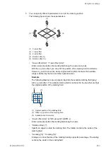
The laser power correction rate of each marking field area is displayed in the image
on the left side.
• Adjust the laser power in the corners of the marking field. Enter a correction value in
the text box for “Top left”, “Top right”, “Bottom right” and “Bottom left”. Alternatively
use the slider and the arrows to adjust the correction value.
The laser power correction rate of each marking field area is displayed in the image
on the left side.
The laser power correction rate for the corners, for example the “Top left” corner, is
the result of multiplying the values of “Top left”, “X-axis (-)” and “X-axis (-)”.
• The laser power value at the center of the marking field is set to 100%.
• Select “Apply”.
The new settings will be updated in the laser marking system.
• Select “Test marking/guide laser” to perform a test marking process with the file
selected in the “Marking settings” screen. Use this function to test the marking result
with the set laser power optimization settings.
• Select “Reset to default” to reset all values to the initial settings.
• To exit the dialog, select “Close” or “X”.
Tip
To determine the appropriate correction values effectively do the following:
• First, set a correction value for the laser power along the x- and y-axis.
• Perform a test marking to check the marking quality with these settings on the actual
marking surface. If necessary, readjust the values.
• Enter correction values for the corners to fine-tune the marking quality.
• Always perform test marking to check if the marking result is as intended.
276
ME-NAVIS2-OP-1


