background image

4.

Press 

[G]

.

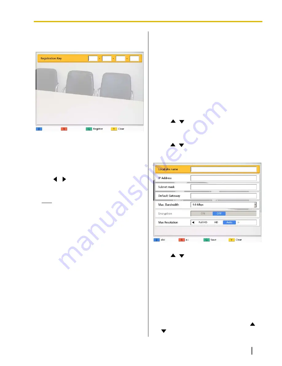
The registration key code input screen is
displayed.

5.

Enter the 16-digit registration key code.

6.

Press 

[G]

.

A dialog box to confirm the saving of settings
and system restart after saving is displayed.

7.

Use 

[

][

]

 to select 

"Yes"

 and press 

[Enter]

.

The system will automatically restart to reflect
changes to system settings.

Note

If the registration key code you entered is
invalid, 

"Failed Registration Key code

authentication."

 is displayed. Repeat the

procedure from step 

5

. If this message is

displayed even when you have correctly
input the registration key code that was
issued, contact your dealer.

Registration is possible only one
registration key code can be registered at
once. To register multiple registration key
codes for enabling multiple features, a
restart is necessary for each registration.

Activated features can also be checked on
the enhanced feature confirmation screen
(Page 88).

Making Local Site
Settings

You can register up to 5 temporary local sites. The
same unit can be used in multiple meeting rooms
without the need to change certain basic network
settings.

Registering a Local Site

1.

Press 

[Menu]

.

The Menu screen is displayed.

2.

Use 

[

][

]

 to select 

"Select local site"

 and

press 

[Enter]

.

The select local site screen is displayed.

3.

Use 

[

][

]

 to select 

"Not Registered"

 and press

[B]

.

The local site settings screen is displayed.

4.

Use 

[

][

]

 to select the following items for input:

"Local site name"

: Enter a name for the local site.

"IP Address"

: Enter an IP address.

If the IP address contains 1 or 2 digit numbers,
enter these numbers as they are. Do not enter
like [.001].
Example: The IP address is [192.168.0.1].

Correct entry: [192.168.0.1]

Wrong entry: [192.168.000.001]

"Subnet mask"

: Enter the subnet mask.

"Default Gateway"

: Enter the IP address of the

default gateway.

"Max. Bandwidth"

: Press 

[Enter]

 and use 

[

]

[

]

 to select the maximum allowed bandwidth to

Document Version  2011-04  

Operating Manual

95

Contacts and Settings

Summary of Contents for KX-VC300

Page 1: ...11 04 In this manual the suffix of each model number e g KX VC600NA is omitted unless necessary Thank you for purchasing this Panasonic product Please read this manual carefully before using this product and save this manual for future use KX VC300 KX VC600 Software File Version 2 21 or later ...

Page 2: ...ge 83 When using Digital Boundary Microphones and an Analog Boundary Microphone together stereo output may be unavailable depending on the connection configuration Page 24 Page 26 Home Electronics style Remote Control Operation and Simple Easy to Understand Graphical User Interface You can make settings and perform operations using familiar remote control operations and a simple easy to understand...

Page 3: ... contact your dealer 5 This service may be unavailable depending on your router s type or your Internet connection environment For details contact your dealer Enhanced Features through the Use of Activation Keys By using an activation key sold separately you can upgrade the features of the KX VC300 Page 71 After you upgrade the features the KX VC300 can initiate 3 party 4 party video conference ca...

Page 4: ...onditions apply to this software Therefore please read license information about GPLs and LGPLs and information about other Open Source Software in the included CD ROM before using this product Also some software parts of this product are licensed under the MOZILLA PUBLIC LICENSE MPL At least three 3 years from delivery of products Panasonic will give to any third party who contacts us at the cont...

Page 5: ...ply See www dtsc ca gov hazardouswaste perchlorate Information on disposal in other countries outside the European Union These symbols are only valid in the European Union If you wish to discard these items please contact your local authorities or dealer and ask for the correct method of disposal Document Version 2011 04 Operating Manual 5 Introduction ...

Page 6: ... Conference 4 party Conference 33 Calling from the Contact List 2 party Conference 3 party Conference 4 party Conference 36 Calling by Entering an IP Address 38 Calling from the Call History 40 Answering a Video Conference Call 43 Connecting to a Non Panasonic Video Conference System 44 Connecting to an MCU 45 Changing the Screen Layout 47 Changing the Screen Layout during a 2 party Video Conferen...

Page 7: ...he MIC Position KX VC600 only 82 Making Remote Control Settings 85 Performing a Network Test 86 Performing Self Diagnosis 86 Performing Remote Maintenance 87 Checking Enhanced Features 88 Making Administrator Menu Settings 88 Logging in to the Administrator Menu 88 Making Language Settings 89 Making Encryption Settings 89 Making Connection Mode Setting 90 Making Software Update Settings 91 Updatin...

Page 8: ...106 Basic Operation 106 Audio 110 System Settings 111 If These Messages Appear 112 Miscellaneous 117 Specifications 118 System Specifications 118 Index 120 8 Operating Manual Document Version 2011 04 Table of Contents ...

Page 9: ...r voltage If you use a cord with an unspecified current rating the unit or plug may emit smoke or become hot to the touch Do not connect the unit to the AC outlet AC extension cords etc in a way that exceeds the power rating of or does not comply with the instructions provided with the AC outlet AC extension cords etc Connect the AC adaptor firmly to the power cord and plug the power cord firmly i...

Page 10: ...ock Do not use a unit in the vicinity of a gas leak to report the leak Do not place the remote control in microwave ovens or on induction cookware Clean the AC plug periodically with a soft dry cloth to remove dust and other debris Do not use the supplied power cord with any other device It may cause fire or electric shock Unplug the unit from the AC outlet and have it serviced by qualified servic...

Page 11: ... remote control Otherwise the batteries may leak CAUTION Power When the unit is not used over an extended period of time take the batteries out of the remote control Otherwise the batteries may leak Do not use the leaked batteries When the unit is not used over an extended period of time switch it off and unplug it If an unused unit is left connected to a power source for a long period degraded in...

Page 12: ...n resulting in injury or fire Dispose of used batteries according to the instructions of your local solid waste officials and local regulations When replace the batteries for the remote control use AA R6 type dry cell Do not install the battery backwards so that the polarity is reversed 12 Operating Manual Document Version 2011 04 For Your Safety ...

Page 13: ...ed high frequency sewing machines electric welders magnets etc Doing so may result in static noise or damage 9 Keep the device at least 10 cm 4 in away from all walls If placed against a wall the device may not be able to ventilate properly which may lead to a system malfunction due to overheating 10 Avoid placing the device in areas with high humidity and exposing it to rain Neither the main unit...

Page 14: ... Data Disclosure over the Network To ensure the security of private conversations only connect the unit to a secure network To prevent unauthorized access only connect the unit to a network that is properly managed Make sure all computers connected to the unit employ up to date security measures To prevent illegal access from the Internet activate a Firewall Privacy and Right of Publicity By insta...

Page 15: ...cy energy and if not installed and used in accordance with the instructions manual may cause harmful interference to radio communications Operation of this equipment in a residential area is likely to cause harmful interference in which case the user will be required to correct the interference at his own expense FCC Caution To assure continued compliance example use only shielded interface cables...

Page 16: ...ries Quantity AC adaptor Part No PNLV6506 1 Power cord 1 Remote control Part No N2QAYB000674 1 Batteries AA dry cell 2 CD ROM included manuals etc 1 Note Product documentation may vary depending on the country area of use 16 Operating Manual Document Version 2011 04 Preparation Preparation ...

Page 17: ...display or speakers If a headset is connected how audio is sent to the other party differs depending on the type of devices connected as follows Connected Device Audio Sent to Other Party Boundary Microphone Audio is picked up only by the headset microphone Audio is not picked up by the Boundary Microphones General purpose microphone Both the general purpose microphones and the headset microphone ...

Page 18: ...rophones not for the Boundary Microphone Audio Out L R jack Page 27 Used to connect an amplifier or active speaker Functional Ground terminal Used to connect a grounding wire for when there is a lot of noise over the connection LAN jack Page 23 Connect a LAN cable USB jack This jack is not available for use RGB terminal Used to connect a computer for sending screens to participants Page 59 Main Ca...

Page 19: ...connect to the display with an HDMI cable Component terminal Page 27 Used to connect to the display with a component video cable DC IN Page 24 Connect the AC adaptor s DC cord Document Version 2011 04 Operating Manual 19 Preparation ...

Page 20: ...ophone during a call so that the other party cannot hear your voice Page 56 Press to display your contact list This can be pressed while the following screens are displayed Home screen Menu screen Computer s screen sub video camera s image when not on a video conference call Press to show your computer s screen on your and the other party s display during a video conference call When not on a vide...

Page 21: ...e designed to provide reasonable protection against harmful interference when the equipment is operated in a commercial environment This equipment generates uses and can radiate radio frequency energy and if not installed and used in accordance with the instructions manual may cause harmful interference to radio communications Operation of this equipment in a residential area is likely to cause ha...

Page 22: ...andby mode Video out to the display is suspended and the status LED turns off Screen standby mode ends when the remote control is operated or when a video conference call is received Notice If screen standby mode ends and no image is visible check to see if the display or video camera s power saving settings are enabled Check each device s manual for more information about its power saving setting...

Page 23: ...e proprietary cable until it clicks If the connector does not click try reconnecting the cable with the top and bottom of the connector reversed Analog Boundary Microphone optional Connect the Analog Boundary Microphone to the MIC Analog jack on the back of the unit using the proprietary cable D Use only the included cable Ensure that the arrow on the connector of the proprietary cable is facing u...

Page 24: ...ose microphones can be used simultaneously Note Make sure that the microphones are placed at least 1 m 3 3 ft away from the display and speakers Do not connect more than 4 Digital Boundary Microphones Doing so will cause all Digital Boundary Microphones to stop working If an Analog Boundary Microphone is also connected all audio input from the Analog Boundary Microphone will also stop working When...

Page 25: ...ophone at the center varies according to the level of surrounding and the number of microphones being used Place microphones accordingly referring to the following table Noise level Micro phone 40 dBsplA a quiet room 45 dBsplA a regular room 50 dBsplA a noisy room 1 approx 3 m approx 9 8 ft approx 2 2 m approx 7 2 ft approx 1 2 m approx 3 9 ft 2 approx 2 8 m approx 9 2 ft approx 1 5 m approx 4 9 f...

Page 26: ...the Analog Boundary Microphone will be monaural Layout examples the gray circle indicates the microphone s range Display 3 m 9 8ft 3 m 9 8ft 3 m 9 8 ft Microphone Microphone Microphone Approx Approx 60 60 Approx 60 About 60 around the connector side is outside the microphone s range About Headset You can connect a headset to the headset jack on the front of the unit A B Headset Note Check the head...

Page 27: ...kers either side of the display as follows Microphone Main video camera Display Speaker Speaker Notice Place the speakers either side of the display If you place the display at the front of the room and the speakers at the back the microphone s left right spatial direction may be reversed and the orientation of the image and sound will not match on the other party s side Connecting the Display wit...

Page 28: ... camera are turned on 1 Press the Power button on the front of the unit The Power LED turns on Then the Status LED starts flashing blue slowly and the Home screen is displayed When the power is turned off the Power LED turns off 1 28 Operating Manual Document Version 2011 04 Preparation ...

Page 29: ...ncryption status is displayed Group Site Displays the name group name assigned to One Touch Connection number 1 through 5 If the name is too long to display it will be shortened and ended with Remote Control ID Displays the remote control ID of the unit when it is set Page 85 Guide Displays operations you can perform with the remote control Status Indication The status of the unit is displayed wit...

Page 30: ...ttings you can change D B A E C Main Video Camera Image Displays the video from the main video camera Unit Information Displays the connection mode unit s name IP address maximum bandwidth and encryption status Note When selecting a local site Page 96 that local site s information connection mode local site name IP address maximum bandwidth and encryption status is displayed Guide Displays operati...

Page 31: ...number of antennas in the icon indicates differing levels of network congestion The icon changes as follows 0 bars The network is very congested 1 bar The network is congested 2 bars The network is slightly congested 3 bars The network is not congested Note If the icon shows only 0 1 bars continuously contact your network administrator During multiple party video conference calls the icon is displ...

Page 32: ... unhide the other party s information duration network status indication 1 and guide displays 1 If the network status indication has been set to not be displayed pressing Full Screen will not show the icon 32 Operating Manual Document Version 2011 04 Preparation ...

Page 33: ...ty video conference calls can be made using the incoming call history You cannot add parties to an existing video conference call During a 3 party 4 party video conference call even if only one party ends the video conference call the rest of the parties will also be disconnected A video conference call will start with only the parties that answered the call For example if only one party answers a...

Page 34: ...ection number 1 to 5 The information registered in the selected One Touch Connection number is displayed 3 Press Start to start the call You can also start the call pressing Enter 4 When you want to end the call press End The Home screen is displayed 34 Operating Manual Document Version 2011 04 Starting a Video Conference ...

Page 35: ...ontact List using and press Enter The contact list screen is displayed Note If you press G the contact list modification screen will be displayed and the entry can be modified Page 75 3 Press Y The speed dial screen is displayed Entries are displayed in speed dial number order 4 With the dial keys enter a speed dial number 1 to 300 5 Press Start to start the call 6 When you want to end the call pr...

Page 36: ...ist screen is displayed The entries are grouped in the index tabs and displayed in alphabetical order of Group Site Note You can also open the contact list screen by pressing Contact while the following screens are displayed Home screen Menu screen Computer s screen sub video camera s image when not on a video conference call 36 Operating Manual Document Version 2011 04 Starting a Video Conference...

Page 37: ...eric button on the remote control to switch to the index tab assigned to that button as shown below Numeric button 1 2 3 4 5 6 7 8 9 0 Index Tab ABC DEF GHI JKL MNO PQRS TUV WXYZ 0 9 4 Press Start to start the call 5 When you want to end the call press End The Home screen is displayed Document Version 2011 04 Operating Manual 37 Starting a Video Conference ...

Page 38: ...video conference call No 3 party video conference call 2 sites 4 party video conference call 3 sites Note When connecting to an MCU or non Panasonic video conference system you cannot make 3 party 4 party video conference calls If you are using the KX VC300 inputting 2 or 3 sites is only available after purchasing an activation key card KX VCS301 to activate multiple party video conference calls P...

Page 39: ...1 Press G The contact list screen is displayed 2 Use to select the contact you want to refer to You can use or the numeric buttons of the remote control to select the displayed tab Page 37 3 Press Enter The display returns to the input screen You cannot enter the IP address using the call history 6 Press Start to start the call You can also start the call by pressing Enter 7 When you want to end t...

Page 40: ...made after purchasing an activation key card KX VCS301 to activate multiple party video conference calls Page 94 For details about the activation key contact your dealer When connecting to non Panasonic video conference systems you can make only 2 party video conference calls using the outgoing call history For video conference calls made using the contact list the contact name is displayed For vi...

Page 41: ...ill be displayed In the outgoing call history if a party is registered in your contact list the contact name is displayed However when calling by entering an IP address Page 38 even if the party is registered in your contact list their IP address is displayed When a contact in the incoming call history is newly added to your contact list the incoming call history will be updated to display the con...

Page 42: ...or the maximum bandwidth setting among all participating parties is displayed in Bandwidth If the video conference call was not established the maximum bandwidth will be blank Depending on the other party Device type may be blank 4 Press Start to start the call 5 When you want to end the call press End The Home screen is displayed 42 Operating Manual Document Version 2011 04 Starting a Video Confe...

Page 43: ...caller is registered in the contact list the caller s group site is displayed When the caller is not registered the caller s IP address or host name is displayed Operation 1 Press Start The video conference begins You can also answer the video conference call by pressing Enter 1 Note If you do not answer a video conference call within approximately 60 seconds the call will be terminated automatica...

Page 44: ...tone during a video conference call Audio sent to the other party is monaural While you are displaying a sub video camera s image you cannot send a still image from the sub video camera Encrypted communication is not supported When connecting to a non Panasonic video conference system both you and the other party must have encryption disabled Page 80 Page 89 Page 96 Communication cannot be encrypt...

Page 45: ...MCU differs depending on the MCU For details contact your dealer You cannot adjust the tone during a video conference call Audio sent to the other party is monaural While you are displaying a sub video camera s image you cannot send a still image from the sub video camera Encrypted communication is not supported When connecting to an MCU encryption must be disabled on both sides Page 80 Page 89 Pa...

Page 46: ...age is displayed If the other party sends tone signals to you sound may be interrupted or a ringing noise may occur 1 1 Enter a tone signal 0 9 or The input field A is displayed A Note The input field can only contain up to 16 characters If you input 17 characters the first character input will not be displayed in the input field but all tone signals will be sent The input field is not displayed u...

Page 47: ... each time you press Layout Layout 1 The other party s image is displayed full screen Layout 2 The other party s image is displayed full screen and your own image is displayed in the upper right subscreen Layout 3 Your own image is displayed full screen 1 A B B A Layout 1 Layout 2 Layout 3 A Other Site B This Site Document Version 2011 04 Operating Manual 47 C h a n g i n g t h e S c r e e n L a y...

Page 48: ... When connecting to an MCU or non Panasonic video conference system images received from the other party may not be displayed in the correct aspect ratio the ratio of the width of the image to its height In this case perform the following operation during the video conference call When the video conference call ends the aspect ratio will return to Auto default 1 Press G The aspect ratio dialog box...

Page 49: ...yout 2 The images are displayed as follows Site 1 upper left Site 2 upper right This Site bottom middle Layout 3 Image of Site 1 is displayed full screen and image of Site 2 is displayed in the upper right subscreen Layout 4 Image of Site 2 is displayed full screen and image of Site 1 is displayed in the upper left subscreen Layout 5 The image of Site 1 is displayed full screen Layout 6 The image ...

Page 50: ...A B C Layout 1 Layout 7 Layout 6 B Layout 2 A C B A B A B Layout 3 B A Layout 4 A Layout 5 A Site 1 B Site 2 C This Site 50 Operating Manual Document Version 2011 04 Changing the Screen Layout ...

Page 51: ...Layout first Page 49 Display Screen Layout Side by Side Layout 1 Site 1 2 Layout 3 Site 1 2 Layout 4 Site 1 Layout 5 Site 2 Layout 6 This Site Layout 7 Example When using Layout 3 B The screen layout will be switched to Layout 5 R The screen layout will be switched to Layout 6 G The screen layout will be switched to Layout 7 When using a secondary video source Page 59 Page 63 the screen layout can...

Page 52: ...The images are displayed as follows Site 1 upper left Site 2 bottom middle Site 3 upper right Layout 2 The images are displayed as follows Site 1 upper left Site 2 lower left Site 3 upper right This Site lower right Layout 3 The image of Site 1 is displayed full screen Layout 4 The image of Site 2 is displayed full screen Layout 5 The image of Site 3 is displayed full screen Layout 6 Your own imag...

Page 53: ...Layout 6 Layout 3 A Site 1 B Site 2 C Site 3 D This site Layout 4 Layout 5 B D A C A B C A D B C 1 Image edges are trimmed and the image is centered Document Version 2011 04 Operating Manual 53 Changing the Screen Layout ...

Page 54: ...All Sites Layout 2 Site 1 Layout 3 Site 2 Layout 4 Site 3 Layout 5 This Site Layout 6 Example When using Layout 3 B The screen layout will be switched to Layout 1 R The screen layout will be switched to Layout 2 G The screen layout will be switched to Layout 6 When using a secondary video source Page 59 Page 63 the screen layout cannot be changed 54 Operating Manual Document Version 2011 04 Changi...

Page 55: ...ecrease the volume of the other party s voice 3 After about 3 seconds the volume level bar disappears Note You can set the volume level of a video conference call before starting the call Page 79 After ending a video conference call the volume level returns to the volume level set before starting the call You cannot adjust the display s volume Document Version 2011 04 Operating Manual 55 A d j u s...

Page 56: ...the Boundary Microphone 1 Press the MIC Mute button An icon appears in the status display area of the screen Page 29 and the LED light on the Boundary Microphone Page 21 becomes red Make sure the color of the LED changes Pressing the MIC Mute button again will unmute the microphone The LED light on the Boundary Microphone Page 21 becomes green Make sure the color of the LED changes Note When multi...

Page 57: ...ise reduction is enabled Pressing Y again will display Whisper Mode OFF and noise reduction is disabled Note Noise reduction is available only when Digital Boundary Microphones are connected You can set whether to enable noise reduction for a video conference call before starting the call Page 81 After a video conference call is finished the noise reduction setting returns to the value set before ...

Page 58: ...there is a high level of ambient noise Music makes sounds with a broad frequency such as music easier to hear 3 After about 3 seconds the tone control dialog box disappears Note You can set the tone of a video conference call before starting the call Page 79 After a video conference call is finished the tone setting returns to the value set before starting the call When connecting to an MCU or non...

Page 59: ...E Data Circuit terminating Equipment Connecting the Computer Connect your computer s monitor output to the back of the unit using a VGA cable Page 18 Make sure the cable used has the correct connector shapes to connect to both your computer and to the unit You can connect or disconnect the computer during a video conference call You can only display one computer s screen at a time Document Version...

Page 60: ...d The computer screen is also shown on the other party s display Note When connecting to an MCU or non Panasonic video conference system the same screen may not be shown on the other party s display depending on the other party s screen layout Ask the other party to change their screen layout to display your computer s screen When connecting to an MCU or non Panasonic video conference system you m...

Page 61: ... party s image When viewing the other party s image the screen layout is fixed to Layout 1 To return to displaying your computer s screen press B When connecting to an MCU or non Panasonic video conference system Even while displaying your computer s screen note that it is also possible for the other party to start sharing their computer s screen If a sub video camera is connected you can also swi...

Page 62: ...puter s screen on your display by pressing PC While the computer s screen is displayed the unit will not enter screen standby mode To return to the Home screen press Camera Main 62 Operating Manual Document Version 2011 04 Displaying Other Video Sources ...

Page 63: ... Data Circuit terminating Equipment Connecting the Sub Video Camera Connect a video camera to the back of the unit using an HDMI cable Page 18 You can connect or disconnect the sub video camera during a video conference call You can only display the image of one sub video camera at a time Only video cameras that can output 1080i resolution using HDMI can be used Document Version 2011 04 Operating ...

Page 64: ...ed The image is also visible on the other party s display Note When connecting to an MCU or non Panasonic video conference system the same image may not be shown on the other party s display depending on the other party s screen layout Ask the other party to change their screen layout to display your sub video camera s image 1 2 64 Operating Manual Document Version 2011 04 Displaying Other Video S...

Page 65: ...the other party s image When viewing the other party s image the screen layout is fixed to Layout 1 To return to displaying your sub video camera s image press B When connecting to an MCU or non Panasonic video conference system Even while displaying your sub video camera s image note that it is also possible for the other party to start sharing their sub video camera s image If a computer is conn...

Page 66: ...ra s image on your display by pressing Camera Sub While the sub video camera s image is displayed the unit will not enter screen standby mode To return to the Home screen press Camera Main 66 Operating Manual Document Version 2011 04 Displaying Other Video Sources ...

Page 67: ...ote The image becomes gradually clear after a black screen is displayed for about 1 second If you press R while the still image is being sent the image taken when you pressed R the second time is sent to other party s display again If the network has low bandwidth and a high rate of packet loss either it will take a long time to display a clear image or a blurred image will be displayed 3 Press G ...

Page 68: ...ating MIC displays the connection status of the Boundary Microphone or headset only The connection status of general purpose microphones is not displayed If the MIC detection setting has been disabled through system settings the connection status of the Boundary Microphone or headset will not be displayed Page 81 2 1 2 Press Back The display returns to the screen in use before the connections stat...

Page 69: ...Status is pressed twice during a video conference call you can press R to switch to the next screen That screen displays the unit name IP address packet loss rate connection bandwidth resolution frame rate and field frequency for the 3 parties displayed under Site 1 Site 2 and Site 3 1 2 1 Frequency is not displayed when connecting to an MCU or non Panasonic video conference system 2 Depending on ...

Page 70: ...2 Press Back The display returns to the screen in use before the step 1 was performed 70 Operating Manual Document Version 2011 04 Displaying the Connection Status ...

Page 71: ...bles the feature for sending images in Full HD resolution Note Once you have activated new features Page 94 they remain activated even after software updates or a system initialization Features can be activated only one at a time Page 94 To activate multiple features you must perform activation multiple times A restart is necessary for each activation If the hardware changes for example if you exc...

Page 72: ...make 3 party 4 party video conference calls unless the multiple party video conference call feature has first been enabled by purchasing an activation key card KX VCS301 Page 94 For details about the activation key contact your dealer 72 Operating Manual Document Version 2011 04 About Enhanced Features ...

Page 73: ...ture for sending images in Full HD 1920 1080i has first been enabled by purchasing an activation key card KX VCS401 Page 94 To enable images to be sent at Full HD resolution change the maximum resolution setting Page 81 Page 96 For details about the activation key contact your dealer Document Version 2011 04 Operating Manual 73 About Enhanced Features ...

Page 74: ...l Enter a speed dial number 1 300 Multi Point Use to select No IP Address Enter an IP address If the IP address contains 1 or 2 digit numbers enter these numbers as they are Do not enter like 001 Example The IP address is 192 168 0 1 Correct entry 192 168 0 1 Wrong entry 192 168 000 001 4 Press G A dialog box to confirm the saving of settings is displayed 5 Use to select Yes and press Enter The co...

Page 75: ...ter The contact list screen is displayed Note To continue entering another contact press B and repeat steps 3 5 6 Press Home The Home screen is displayed Editing Contact Information 1 Press Menu The Menu screen is displayed 2 Use to select Contact List and press Enter The contact list screen is displayed 3 Use to select the contact you want to edit You can use or the numeric buttons of the remote ...

Page 76: ...tory Note If a host name is displayed in the Site column of the call history the party cannot be registered in your contact list 1 Press Menu The Menu screen is displayed 2 Use to select Call History and press Enter The outgoing call history screen is displayed Note To refer to the incoming call history press G 3 Use to select the single party entry you want to add as a contact and press B The con...

Page 77: ...sing an activation key card KX VCS301 to activate multiple party video conference calls Page 94 For details about the activation key contact your dealer 1 Press Menu The Menu screen is displayed 2 Use to select Call History and press Enter The outgoing call history screen is displayed 3 Use to select the multiple party entry you want to add as a multiple party contact and press B The contact list ...

Page 78: ...splayed Setting the Date and Time 1 Press Menu The Menu screen is displayed 2 Use to select Settings and press Enter The system settings screen is displayed 3 Use to select Set Date Time and press Enter The date time settings screen is displayed 4 Use to select the item and input information Enter the year 4 digits month 1 2 digits day 1 2 digits time 24 hour display and select the date format Mon...

Page 79: ...nd Settings 1 Press Menu The Menu screen is displayed 2 Use to select Settings and press Enter The system settings screen is displayed 3 Use to select Sound Settings and press Enter The sound settings screen is displayed 4 Use to select the following items for input Welcome Screen Vol Press Enter and use to select the volume level Low Medium default or High played at the start up Ringback Tone Vol...

Page 80: ...0 Mbps 6 0 Mbps 7 0 Mbps 8 0 Mbps 9 0 Mbps default 10 0 Mbps Note The maximum bandwidth during a video conference call adjusts to that of the party that has set the lowest bandwidth for the maximum bandwidth setting among all participating parties You cannot select a value that is higher than the maximum bandwidth set by the dealer For details contact your dealer When you make a 3 party video conf...

Page 81: ... select whether to display the guide when a video conference call begins ON default Displays the guide OFF Hides the guide Noise reduction KX VC600 only Use to select whether to enable noise reduction when a video conference call begins ON Enables noise reduction OFF default Disables noise reduction Call Limit time Enter the maximum length of time for the duration of a video conference call in hou...

Page 82: ...se to select System Info and press Enter The unit information screen is displayed Page 69 5 Press Home The Home screen is displayed Setting the MIC Position KX VC600 only You can specify where a Digital Boundary Microphone is conceptually positioned relative to the display When sounds are transmitted to another party they are played in accordance with the specified positions which creates a stereo...

Page 83: ...settings screen is displayed 6 Use to select the Digital Boundary Microphone you want to configure and press Enter 7 Use to select the Digital Boundary Microphone s relative position Left side Sounds on left side are played Right side Sounds on right side are played Center Mono All sounds are played through both the left and right speakers at the same volume Center stereo Sounds centered on the mi...

Page 84: ...ide Note Make some noise near the Digital Boundary Microphone is displayed to indicate which Digital Boundary Microphone picks up the noise is not displayed when the Digital Boundary Microphone is mute is not displayed when multiple Digital Boundary Microphones pick up the sound at the same time When the Digital Boundary Microphone is mute the sound made by pressing the MIC Mute button might make ...

Page 85: ...fault ID2 ID3 for the unit Check ID mismatch Use to select ON default or OFF When ON is selected if the unit receives a signal from a remote control that has an ID different from the one specified on the Home screen a warning is displayed Follow the procedures on the screen to change the remote control ID When OFF is selected even if the unit receives a signal from a remote control that has an ID ...

Page 86: ... is displayed 2 Use to select Settings and press Enter The system settings screen is displayed 3 Press The second page is displayed 4 Use to select Network Test and press Enter The network test screen is displayed 5 Enter an IP address If the IP address contains 1 or 2 digit numbers enter these numbers as they are Do not enter like 001 Example The IP address is 192 168 0 1 Correct entry 192 168 0 ...

Page 87: ...to Standard 6 Press R The self diagnosis ends Note If you do not press R the self diagnosis will automatically end after about 10 minutes 7 Press Home The Home screen is displayed Performing Remote Maintenance The following operation is for performing remote maintenance by your dealer After performing the operation you cannot use the unit until remote maintenance is finished However turning the po...

Page 88: ...ution is enabled KX VC300 only None No features have been activated 5 Press Home The Home screen is displayed Making Administrator Menu Settings Note If a video conference call is received while data is being entered data entry is interrupted and any unsaved data is lost Logging in to the Administrator Menu 1 Press Menu The Menu screen is displayed 2 Use to select Settings and press Enter The syst...

Page 89: ...g so may cause you to become unable to communicate with other parties There is a danger that encryption settings will be changed by a third party Therefore be careful when managing the administrator password and giving users the authority to change encryption settings If an encryption key is not set you cannot enable encryption Be aware that if encryption is disabled eavesdropping might be possibl...

Page 90: ...ryption Key does not match the other party s the video conference call will not start even if encryption is enabled When the encryption key is displayed as asterisks pressing Y deletes all asterisks at once 4 Press G A dialog box to confirm the saving of settings is displayed 5 Use to select Yes and press Enter The admin menu screen is displayed 6 Press Home The Home screen is displayed Making Con...

Page 91: ...ftware on start up If updates are available a dialog box is displayed on the Home screen When OFF is selected the unit will not automatically look up the DNS server or proxy server to see if there are updates for your software on start up 4 Press G A dialog box to confirm the saving of settings is displayed 5 Use to select Yes and press Enter The admin menu screen is displayed 6 Press Home The Hom...

Page 92: ...update fails an error message is displayed Press Enter to restart the system Please try the following a Check that the DNS server s IP address Page 78 or the proxy server s IP address and proxy port Page 91 are correct and then try updating the software again b If the above step is unsuccessful try updating the software again later The network may be currently very busy If the retry fails several ...

Page 93: ...ssword settings screen is displayed 4 Use to select the following items and enter a password 4 10 digits Current password Enter the current password default 00000000 New password Enter the new password Retype new password Enter the new password again Note Please change the default login password the first time the unit is installed Be sure to keep the password safe 5 Press G A dialog box to confir...

Page 94: ...PR ID 1 Login to the administrator menu Page 88 The admin menu screen is displayed 2 Press The second page is displayed 3 Use to select Enhancement and press Enter The software enhancement screen is displayed Check the field MPR ID A A To Register the Registration Key Code Registering the registration key code you acquired activates the enhanced features 1 Login to the administrator menu Page 88 T...

Page 95: ... the enhanced feature confirmation screen Page 88 Making Local Site Settings You can register up to 5 temporary local sites The same unit can be used in multiple meeting rooms without the need to change certain basic network settings Registering a Local Site 1 Press Menu The Menu screen is displayed 2 Use to select Select local site and press Enter The select local site screen is displayed 3 Use t...

Page 96: ... the maximum display resolution of the main video camera and sub video camera used during a video conference call Full HD Maximum resolution 1920 1080i This mode switches the display resolution according to the condition of the network HD default for KX VC300 Maximum resolution 1280 720p This mode switches the display resolution according to the condition of the network Auto default for KX VC600 T...

Page 97: ...turn off the power and then turn it back on or use the following procedure 1 Repeat steps 1 2 2 Use to select the currently selected local site 3 Press Y A dialog box to confirm whether you want to return to the site set on the system settings screen is displayed 4 Use to select Yes and press Enter The Home screen is displayed Editing Local Site Information 1 Press Menu The Menu screen is displaye...

Page 98: ...select local site screen is displayed 3 Use to select the local site you want to delete 4 Press R A dialog box to confirm deletion is displayed 5 Use to select Yes and press Enter The select local site screen is displayed 6 Press Home The Home screen is displayed 98 Operating Manual Document Version 2011 04 Contacts and Settings ...

Page 99: ...input depends on which language is selected through system settings Press the indicated button repeatedly to cycle through the characters and numbers assigned to that button until the character you want to input is displayed If you want to input another character using the same button press to move the input cursor to the right Document Version 2011 04 Operating Manual 99 I n p u t Input ...

Page 100: ...er Mode 1 1 1 1 1 1 ABCabc2 AÀÁÂÃÄÅ ÆBCÇaàá âãäåæbcç 2 aàáâãäåæ bcçAÀÁ ÃÄÅÆBC Ç2 2 DEFdef 3 3 GHIghi4 4 JKLjkl5 5 MNOmno6 6 PQRSpqr s7 7 TUVtuv8 8 WXYZwxy z9 9 0 Space 0 _ 1 abcABC2 defDEF3 ghiGHI4 jklJKL5 JKLjkl5 jklJKL5 mnoMNO6 pqrsPQR S7 tuvTUV8 wxyzWXY Z9 0 Space 0 Space 0 Space 0 Space 0 Space _ _ _ _ _ _ DEÈÉÊËF deèéêëf3 deèéêëfD EÈÉÊËF3 GHIÍghií4 ghiíGHIÍ4 MNÑOÒÓ ÔÕÖØŒ mnñoòóô õöøœ6 mnñoòó...

Page 101: ...2 AÀÁÂÃÄÅ ÆBCÇaàá âãäåæbcç 2 aàáâãäåæ bcçAÀÁ ÃÄÅÆBC Ç2 2 DEÈÉÊËF deèéêëf 3 3 GHIÎÏghiîï 4 4 JKLjkl5 5 MNOÔŒ mnoôœ6 6 PQRSpqr s7 7 TUÙÛÜVt uùûüv8 8 WXYZwxy z9 9 0 Space 0 _ 1 aàâæbcçA ÀÂÆBCÇ2 deèéêëfD EÈÉÊËF3 ghiîïGHIÎÏ 4 jklJKL5 JKLjkl5 jklJKL5 mnoôœM NOÔŒ6 pqrsPQR S7 tuùûüvTU ÙÛÜV8 wxyzWXY Z9 0 Space 0 Space 0 Space 0 Space 0 Space _ _ _ _ _ _ DEÈÉÊËF deèéêëf3 deèéêëfD EÈÉÊËF3 GHIÍghií4 ghiíGHIÍ...

Page 102: ...1 AÁBCaáb c2 AÀÁÂÃÄÅ ÆBCÇaàá âãäåæbcç 2 aàáâãäåæ bcçAÀÁ ÃÄÅÆBC Ç2 2 DEÉFdeé f 3 3 GHIÍghií4 4 JKLjkl5 5 MNÑOÓm nñoó6 6 PQRSpqr s7 7 TUÚÜVtu úüv8 8 WXYZwxy z9 9 0 Space 0 _ 1 aábcAÁB C2 deéfDEÉ F3 ghiíGHIÍ4 jklJKL5 JKLjkl5 jklJKL5 mnñoóMN ÑOÓ6 pqrsPQR S7 tuúüvTUÚ ÜV8 wxyzWXY Z9 0 Space 0 Space 0 Space 0 Space 0 Space _ _ _ _ _ _ DEÈÉÊËF deèéêëf3 deèéêëfD EÈÉÊËF3 GHIÍghií4 ghiíGHIÍ4 MNÑOÒÓ ÔÕÖØŒ mn...

Page 103: ...ed Deleting an Input Character Press Y to delete an input character The character deleted depends on the position of the cursor If the cursor is to the right of the last character in the line the last character will be deleted If the cursor is within a line of characters the character to the right of the cursor will be deleted Inserting Characters Use to move the cursor to the position where you w...

Page 104: ...Control Batteries 1 Open the cover 2 Take out the AA batteries 3 Insert new batteries AA dry cell minus side first then close the cover 104 Operating Manual Document Version 2011 04 M i s c e l l a n e o u s Miscellaneous ...

Page 105: ...h a neutral household cleaning agent using a well wrung damp cloth Then wipe down the unit with a dry soft cloth Do not use the following when cleaning the unit They may cause unit discoloration or damage Petroleum Scouring powder Alcohol Thinner Benzene Wax Hot water Powder soap If using a chemically treated cleaning cloth be sure to follow all accompanying directions and warnings Document Versio...

Page 106: ...or can set the length of time until the unit enters screen standby mode Page 92 When connecting a device equipped with HDCP High bandwidth Digital Content Protection only a blue or blue black screen may be displayed If an image is not correctly displayed do not connect an HDCP equipped device The area at the edges of the screen is not displaying properly The display is not set to show the full ima...

Page 107: ...ge 17 The remote control ID differs between the unit and the remote control Change the settings so that the remote control ID of the unit and the remote control match Perform the following procedure 1 Turn off the unit and restart it The Home screen is displayed Check the remote control ID of the unit Page 29 Note If the remote control ID is not displayed on the Home screen contact your dealer 2 P...

Page 108: ... Page 95 The local site settings are incorrect Confirm the local site settings Specify the settings that are appropriate for your usage environment Page 95 The IP address is not entered correctly Confirm that the other party s IP address is correctly entered The Internet connection is not established Some hubs routers etc can take 10 seconds or more to establish an Internet connection A video conf...

Page 109: ...e contact your dealer There may be a problem with your communication lines Contact your dealer The maximum bandwidth changes during a video conference call The maximum bandwidth during a video conference call adjusts to that of the party that has set the lowest bandwidth for the maximum bandwidth setting among all participating parties If there is a problem with your communication lines contact yo...

Page 110: ...Microphones is disabled To use the Boundary Microphones disconnect the headset There may be a problem with your communication lines Contact your dealer The sound cuts out You are too far from a microphone Speak close to a microphone The microphone or unit is being moved during a video conference call Do not move the unit or the microphone during a video conference call The microphone is being obst...

Page 111: ...eakers of the other party are not properly positioned Ask the other party to position speakers on either side of the display When the MIC position is set automatically if the other party places the display at the front of the room and the speakers at the back the microphone s left right spatial direction may be reversed and the orientation of the image and sound will not match The MIC positions se...

Page 112: ...ter the IP address correctly in the format XXX XXX XXX XXX decimal values separated by periods For values of only 1 or 2 digits enter these numbers as they are Do not enter like 001 Example The IP address is 192 168 0 1 Correct entry 192 168 0 1 Wrong entry 192 168 000 001 Multicast or broadcast addresses cannot be used Invalid Subnet mask The input subnet mask is invalid Enter a valid subnet mask...

Page 113: ...HDMI output to 1080i Safe mode If is pressed the system enters safe mode after restart A standard definition 640 480p 720 480p video camera signal has been detected Change the video camera s resolution to HD 1920 1080i Note If you enter Safe Mode during a video conference call the call will be disconnected Check main camera setting Check camera Set camera operating frequency to nHz Safe mode If is...

Page 114: ...Call Failed due to combination mismatch In a multiple party video conference call one or more of the parties is incompatible Check the software version of all parties Update the unit with the older software version so that the versions match Call Failed due to unsupported product or other error An unsupported feature was used Check the software version of all parties Update the unit with the older...

Page 115: ...FF for Check ID mismatch Page 85 The IP Address is invalid Please enter a valid IP Address The IP address contains an invalid value Enter the IP address correctly The correct format is XXX XXX XXX XXX dotted format decimal notation If the IP address contains 1 or 2 digit numbers enter these numbers as they are Do not enter like 001 Example The IP address is 192 168 0 1 Correct entry 192 168 0 1 Wr...

Page 116: ...ing to an MCU or non Panasonic video conference system the video conference call was disconnected for an unknown reason Wait a while and then try making the video conference call again If video conference calls get disconnected repeatedly contact your dealer Call failed due to insufficient bandwidth setting on called site The other party s maximum bandwidth is set to a value that cannot support 3 ...

Page 117: ...deo camera to the unit again A standard definition 640 480p 720 480p display signal has been detected Disconnect the display from the unit and reset the unit by turning off its power then turning it back on Make sure to connect a HD 1920 1080i display to the unit The field frequency of the video camera or display you are using is different from the field frequency setting of the unit Use a video c...

Page 118: ...p to 4 Boundary Microphones KX VCA001 only Sound Pickup Method KX VCA001 Stereo Monaural 1 KX VCA002 Stereo Monaural 2 Transmission Call Control SIP Other AV QoS Call Control Encrypted Transmission AES External Interface Video Inputs HDMI Camera 2 RGB PC 1 Switchable 3 inputs Video Output HDMI 1 RCA Component 1 Audio Input KX VC300 Analog Boundary Microphone port 1 RCA Stereo 1 Stereo mini plug He...

Page 119: ...perating Temperature 0 C 40 C 32 F 104 F 1 Either output can be set through system settings Page 83 However when using together with an Analog Boundary Microphone or when connecting to an MCU or non Panasonic video conference system stereo output may not be available Page 24 2 When using together with an Analog Boundary Microphone or when connecting to an MCU or non Panasonic video conference syst...

Page 120: ...ction setting 80 Contacts adding 74 Contacts deleting 76 Contacts editing 75 D Date and Time setting 78 E Enabling Multiple Party Video Conference Calls KX VC300 only 72 Enabling the Sending of Images in Full HD Resolution KX VC300 only 73 Encryption setting 89 F For Your Safety 9 H Headset 26 I Inputting Letters and Numbers 99 K KX VCS301 Activation Key Card for Multiple Party Video Conference Ca...

Page 121: ...etting 79 Specifications system 118 Sub Video Camera viewing 63 System Initialization performing 93 T Tone Adjusting 58 Troubleshooting 106 U Unit Information viewing 69 82 Unit Name setting 78 V Volume adjusting 55 Document Version 2011 04 Operating Manual 121 Index ...

Page 122: ...the product to the address listed in the Limited W Consult your authorized Panasonic dealer for detailed instructions http www panasonic ca One Panasonic Way Secaucus New Jersey 07094 http www panasonic com csd Copyright This material is copyrighted by Panasonic System Networks Co Ltd and may be reproduced for internal use only All other reproduction in whole or in part is prohibited without the w...

Reviews: