149
Options
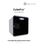
The printer controller board ships with the following memory configuration:
•
The DRAM SIMM connectors numbered CN7 and CN8 are reserved for the printer’s memory.
•
The remaining two connectors CN9 and CN10 are empty and reserved for the PS SIMM.
To install a PS SIMM, you will need to remove and replace the printer cover. For instructions, see
“Removing and replacing the printer cover” on page 136
.
To install a PS SIMM:
1
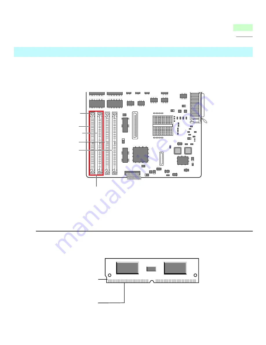
Unpack the PS SIMM.
Do not touch the connector edge on the PS SIMM.
Installing a PS SIMM
CN 9
PS SIMM
Connector
The two slots are reserved for the PS SIMM.
CN 10
CN 7
CN 8
Notch
Connector
edge