98
9.2.
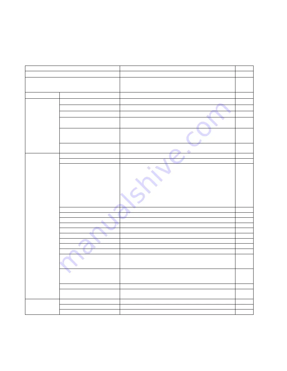
List of Functions for Service Utility
Service Utility item list is as follows.
Note:
When two or more scanners are connected to a PC, execute
“Select Scanner”
to specify the scanner before evaluating.
The procedure is as follows.
1. Click
“Select Scanner”
on the main menu.
2. Select the product number of the scanner to evaluate.
Item
Purpose
Remarks
Scanner Status
*2
Used to indicate scanner status (Ready, Error, or Caution)
2
Scanner Information
*2
Used to indicate scanner information such as Model, firmware
version, board revision, memory size, interface, Interface
condition, etc.
2
Scanner Counter
Update Counters
*2
Used to update the values of System Counter.
1, 6
Scanner Condition Sleep Mode
*2
Used to set
“Waiting Time”
before entering the Sleep Mode
1
Clean Imprinter
*1 *2
Used to clean the ink jet head of the imprinter
6
Buzzer Setting
*2
Used to set the Buzzer ON/OFF condition
1
User Shading
*2
Used to execute shading correction at the user side, or to restore
the shading data to the default (Factory-setting)
4
Roller Maintenance
*2
Used to set the number of the document scanning that enables
the Service Utility to inform the caution information (roller
replacement timing and roller cleaning timing)
1, 3
Set Default
Used to set
“Sleep Mode”
,
“Caution Setting”
, and
“Feed Speed”
to the default
3
Test 1
LED
Used to periodically light the indicators on the front cover
5
Key / Sensor
Used to do keys' or sensors' ON/OFF test
5
Feed Motor
Used to check the operation of the motor periodically rotating in
the paper-feed direction and its reverse direction
Note:
• Rotating in the paper-feed direction will allow the Paper
Feed Roller Module to go down to perform the paper-feed
function.
• Rotating in the reverse direction will allow the Paper Feed
Roller Module to rise to perform the paper-separation
function.
5
Conveyor Motor
Used to check Conveyor Motor rotation
5
DFP Pressure Drive
Used to check DFP Pressure Motor rotation
5
Hopper Drive
Used to check the operation of the Hopper Motor Operation
Feed
Used to check paper feed condition
5
LCD Test
Used to check the LCD (S5076H only)
Sleep Mode
Used to check whether the sleep mode function works properly
5
CIS LED Level
This Item is not used.
CIS Level
This Item is not used.
5
CIS Black Level
This Item is not used.
Focus
Used to check whether CIS operates normally by outputting the
CIS's output level or whether a dust is attached on the Scanning
Glass
5
Double Feed
Used to check the level of the Double Feed Detector (R)
(Response level) after setting the ultrasonic emission level of the
Double Feed Detector (G)
5
Memory
Used to execute memory R/W test
5
Ionizer
Used to check whether ON/OFF (Enable/Disable) control to
output Ionizer properly operates.
5
Test 2
Deskew Assist Motor
Used to check Deskew Assist Motor rotation (S5076H only)
Exit Motor
Used to check Deskew Assist Motor rotation (S5076H only)
Platen Motor
Used to check Platen Motor rotation
Summary of Contents for KV-S5046H
Page 8: ...8 3 COMPONENT IDENTIFICATION 3 1 Main Part Names and Locations ...
Page 9: ...9 ...
Page 19: ...19 5 SECTIONAL VIEW 5 1 Bottom Block ...
Page 20: ...20 5 2 Back Block ...
Page 21: ...21 5 3 Upper Block ...
Page 22: ...22 5 4 Lower Block 5 4 1 Mechanical Parts ...
Page 23: ...23 5 4 2 Boards ...
Page 39: ...39 Location of Reflectors G G G Reflectors ...
Page 48: ...48 ...
Page 49: ...49 ...
Page 76: ...76 3 Remove the screw 4 While releasing the 3 claws pull the Left Cover forward ...
Page 79: ...79 5 Pull in each directions and remove rubber parts 6 Component Parts ...
Page 86: ...86 5 Disconnect the connector 6 Pull and remove the Conveyor Motor ...
Page 89: ...89 6 Disconnect the Flat cable 7 Remove the CIS B 8 Remove Glass Assy See 8 4 2 ...
Page 92: ...92 4 Pull out the Drive Roller 2 in the direction of the arrow ...
Page 104: ...104 ...
Page 132: ...132 ...
Page 133: ...133 ...
Page 134: ...134 ...
Page 224: ...224 14 PARTS LOCATION AND MECHANICAL PARTS LIST ...
Page 241: ...241 14 7 Packing 466 468 461 462 464 467 467 456 457 460 463 465 469 458 459 ...


