112
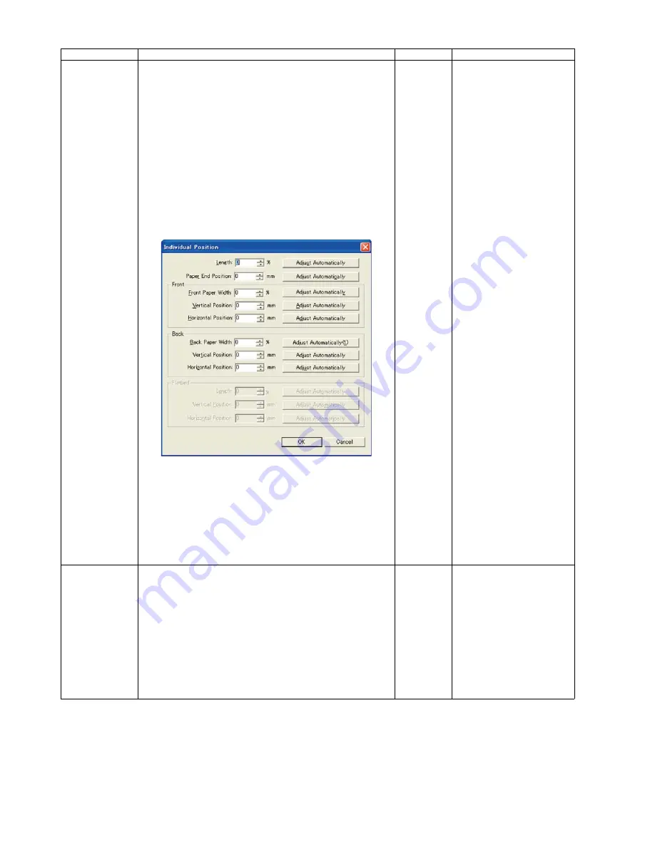
Individual Position 1. Adjust Automatically.
a. Set test chart A (Part No.: See 14.8.) on the Hopper.
b. Click
“Individual Position”
on the main menu.
c. Click one of 8
“Adjust Automatically”
buttons on the
“Individual Position”
dialog box to execute the
adjustment.
d. Check the result.
e. Click
“OK”
to finish the adjustment.
f. Click
“OK”
to return to the main menu.
2. Adjust Manually.
a. Click
“Individual Position”
on the main menu.
b. Change the parameter (mm,%) on the
“Individual
Position”
dialog box as required. (Refer to Remarks.)
c. Click
“OK”
to renew the setting, and to return to the
main menu.
—
1.
“Adjust Automatically”
a. Length
b. Paper End Position
c. Front Paper Width
d. Front V. Position
e. Front H. Position
f. Back Paper Width
g. Back V. Position
h. Back H. Position
2. Adjust Manually
(Length)
+: Increasing the number
makes the scanning
document length shorter.
(Vertical Position)
+: Increasing the number
makes the document
scanning position shifted
upward.
(Horizontal Position)
+: Increasing the number
makes the document
scanning position shifted
to the left.
(Paper End Position)
+: On the LC (Length
Control) mode,
increasing the number
allows the paper-end
timing to be earlier
.
(Width)
-: Decreasing the number
extends the scanning
document width.
Note
If the appropriate
scanning position can
not be obtained by any
of the manual
adjustments, check
installation.
Double Feed
1. Adjust Automatically.
a. Set the Shading Sheet (Part No.: See 14.8.) on the
Hopper in portrait orientation, sliding the Document
Guides so that they match the document width.
b. Click
“Double Feed”
in
“Adjust”
section on the main
menu.
c. Click
“Adjust Automatically”
on the
“Double Feed
Sensor”
dialog box to adjust the double feed sensitivity.
d. Check the result.
e. Click
“OK”
to finish the adjustment.
f. Click
“OK”
on the
“Double Feed Sensor”
dialog box to
return to the main menu.
—
Item
Operation
Default
Remarks
Summary of Contents for KV-S5046H
Page 8: ...8 3 COMPONENT IDENTIFICATION 3 1 Main Part Names and Locations ...
Page 9: ...9 ...
Page 19: ...19 5 SECTIONAL VIEW 5 1 Bottom Block ...
Page 20: ...20 5 2 Back Block ...
Page 21: ...21 5 3 Upper Block ...
Page 22: ...22 5 4 Lower Block 5 4 1 Mechanical Parts ...
Page 23: ...23 5 4 2 Boards ...
Page 39: ...39 Location of Reflectors G G G Reflectors ...
Page 48: ...48 ...
Page 49: ...49 ...
Page 76: ...76 3 Remove the screw 4 While releasing the 3 claws pull the Left Cover forward ...
Page 79: ...79 5 Pull in each directions and remove rubber parts 6 Component Parts ...
Page 86: ...86 5 Disconnect the connector 6 Pull and remove the Conveyor Motor ...
Page 89: ...89 6 Disconnect the Flat cable 7 Remove the CIS B 8 Remove Glass Assy See 8 4 2 ...
Page 92: ...92 4 Pull out the Drive Roller 2 in the direction of the arrow ...
Page 104: ...104 ...
Page 132: ...132 ...
Page 133: ...133 ...
Page 134: ...134 ...
Page 224: ...224 14 PARTS LOCATION AND MECHANICAL PARTS LIST ...
Page 241: ...241 14 7 Packing 466 468 461 462 464 467 467 456 457 460 463 465 469 458 459 ...


