109
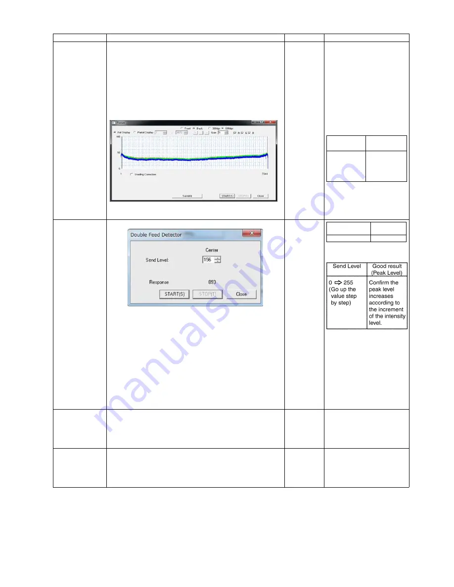
Focus
Operation
1. Click
"Focus"
on the main menu.
2. Select a side (Front or Back) and resolution(300dpi
or 600dpi).
3. Set the value of Gain.(Value:0 to 15)
4. As required, set
"Shading Correction"
by checking check-
box so that the image sensor output-level after shading
correction can be seen.
5. Click
"START"
on the
"Focus"
dialog box to monitor the
image sensor waveform.
6. Click
“STOP”
on the
"Focus"
dialog box to finish the test.
7. Click
"Close"
to return to the main menu.
—
Note:
This operation indi-
cates a sensor output
waveform to check
whether there is any
partial depression of the
level.
If the waveform has any
partial depression, clean
the Scanning Glass(F)
or Scanning Glass(B).
Double Feed
1. Click
“Double Feed”
for
“Test”
item on the main menu.
2. Set
“Send Level”
on
“Double Feed Sensor”
dialog box.
3. Push the ADF Door Release to open the ADF Door.
And hold a piece of clean white paper between Scanning
Glass (F) and Scanning Glass (B), and then close the ADF
Door.
4. Click
“START”
on the
“Double Feed Sensor”
dialog box to
start the double feed sensor’s sensitivity test.
5. Check whether the peak level is within the specification.
(See Remarks.)
6. Click
“STOP”
to finish this test.
7. Push the ADF Door Release to open the ADF Door.
And remove the white paper, and then close the ADF Door.
8. Click
“Close”
to return to the main menu.
—
Memory
1. Click
“Memory”
on the main menu.
2. Click
“START”
on the
“Memory”
dialog box to start Memory
Read / Write Test.
3. Check the result.
4. Click
“Close”
to return to the main menu.
—
For details on Error Codes,
refer to Sec. 9.3.2.
Ionizer
1. Click
“Ionizer”
on the main menu.
2. Click
“START”
on the
“Ionizer Test”
dialog box to start
Ionizer ON /OFF Test.
3. Check the result.
4. Click
“Close”
to return to the main menu.
—
Note:
This test does not starts
until the ADF Door is
closed.
Item
Operation
Default
Remarks
Gain
Good Result
(Level)
Front
0 to 15
20 or more
Back
0 to 15
20 or more
Send Level
Good result
(Peak Level)
Level: 50 to 255 860 or more
Summary of Contents for KV-S5046H
Page 8: ...8 3 COMPONENT IDENTIFICATION 3 1 Main Part Names and Locations ...
Page 9: ...9 ...
Page 19: ...19 5 SECTIONAL VIEW 5 1 Bottom Block ...
Page 20: ...20 5 2 Back Block ...
Page 21: ...21 5 3 Upper Block ...
Page 22: ...22 5 4 Lower Block 5 4 1 Mechanical Parts ...
Page 23: ...23 5 4 2 Boards ...
Page 39: ...39 Location of Reflectors G G G Reflectors ...
Page 48: ...48 ...
Page 49: ...49 ...
Page 76: ...76 3 Remove the screw 4 While releasing the 3 claws pull the Left Cover forward ...
Page 79: ...79 5 Pull in each directions and remove rubber parts 6 Component Parts ...
Page 86: ...86 5 Disconnect the connector 6 Pull and remove the Conveyor Motor ...
Page 89: ...89 6 Disconnect the Flat cable 7 Remove the CIS B 8 Remove Glass Assy See 8 4 2 ...
Page 92: ...92 4 Pull out the Drive Roller 2 in the direction of the arrow ...
Page 104: ...104 ...
Page 132: ...132 ...
Page 133: ...133 ...
Page 134: ...134 ...
Page 224: ...224 14 PARTS LOCATION AND MECHANICAL PARTS LIST ...
Page 241: ...241 14 7 Packing 466 468 461 462 464 467 467 456 457 460 463 465 469 458 459 ...


