8.4.2.
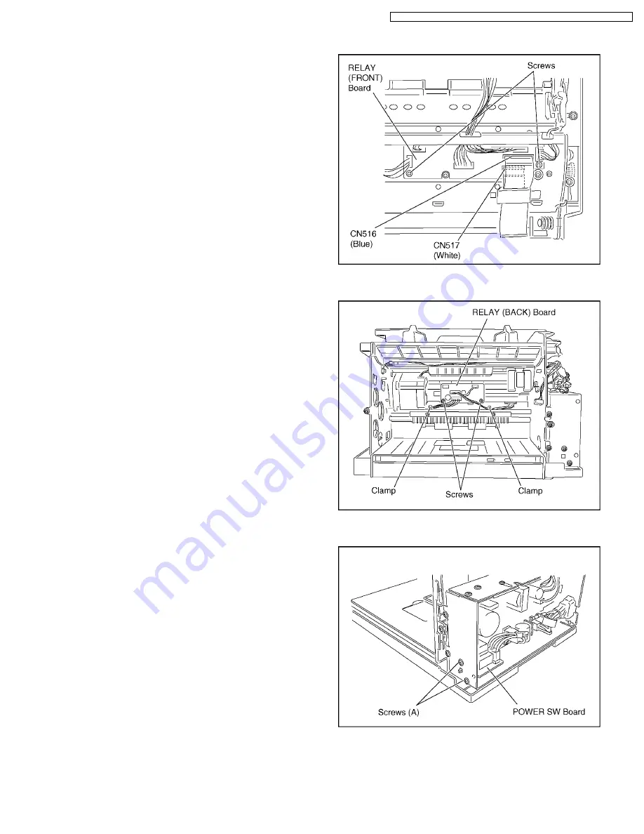
RELAY (FRONT) Board
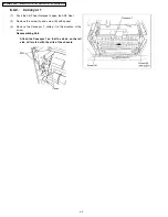
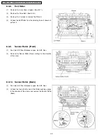
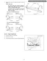
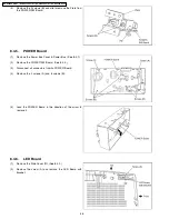
(1)
Remove the Rear Cover. (See 8.2.4.)
(2)
Disconnect all connectors from/to RELAY (FRONT) Board
and remove it.
(3)
Remove the 2 screws.
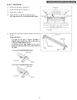
Reassembling Note
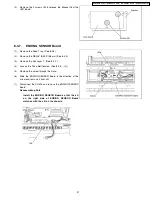
Reassemble the connectors to CN516 and CN517,
paying attention to the direction to insert.
8.4.3.
RELAY (BACK) Board
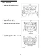
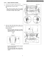
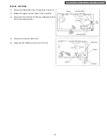
(1)
Remove the Inner Cover (Upper). (See 8.2.7.)
(2)
Remove the 2 screws.
(3)
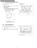
Release the cables from the clamps.
(4)
Disconnect all connectors from/to RELAY (BACK) Board
and remove it.
Note
Be careful when disconnecting the all connectors
on the RELAY (BACK) Board.
8.4.4.
POWER SW Board
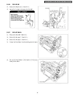
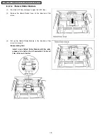
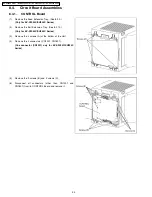
(1)
Remove the Power Box Cover. (See 8.3.1. - (1), (2))
(2)
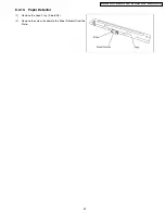
Remove the 2 screws (A).
(3)
Disconnect the CN809 and CN810.
55
KV-S2025C Series / KV-SU225C Series / KV-S2045C Series / KV-SU245C Series
Summary of Contents for KV-S2025C
Page 96: ...96 KV S2025C Series KV SU225C Series KV S2045C Series KV SU245C Series ...
Page 114: ...KV S2025C Series KV SU225C Series KV S2045C Series KV SU245C Series 114 ...
Page 116: ...14 1 Exterior 116 KV S2025C Series KV SU225C Series KV S2045C Series KV SU245C Series ...
Page 118: ...14 2 Chassis and Base 118 KV S2025C Series KV SU225C Series KV S2045C Series KV SU245C Series ...
Page 120: ...14 3 Hopper Unit 120 KV S2025C Series KV SU225C Series KV S2045C Series KV SU245C Series ...
Page 122: ...14 4 Power Unit 122 KV S2025C Series KV SU225C Series KV S2045C Series KV SU245C Series ...

