background image

使用前

准备

操作

其他

CN

7

警告

禁止


不使用时,将电源插头从插座中拔出。

如不遵守,将会因绝缘老化而导致触电或漏电起火。

禁止接触


打雷后,请勿触摸本产品及电源插头。

否则会触电。

禁止拆解


不得改装。且不可拆解或维修。

否则可能会引起火灾、触电、人员受伤。


维修事宜请咨询您所购买的销售店或本公司咨询窗口。

禁止淋水

请勿进行以下操作。


请勿在淋雨或潮湿场所使用或放置。


使用时不要浸入水中。

否则可能会出现冒烟、起火、破裂。

禁止湿手


请勿用湿手从插座中插拔电源插头。

否则可能会触电。

EY9310ADA202.indb   7

EY9310ADA202.indb   7

2023/12/07   19:01:39

2023/12/07   19:01:39

Summary of Contents for EYADA Series

Page 1: ...EYADA EYADA212XC EYADA218XC EYADA407XC 2 4 10 13 17 22 c 25 u 32 n 39 b 41 44 49 51 52 54 56 CN EY9310ADA202 indb 1 EY9310ADA202 indb 1 2023 12 07 19 01 38 2023 12 07 19 01 38...

Page 2: ...CN 2 4 1 P 25 P 20 21 P 35 P 17 P 42 PLC P 38 P 44 EY9310ADA202 indb 2 EY9310ADA202 indb 2 2023 12 07 19 01 38 2023 12 07 19 01 38...

Page 3: ...CN 3 1 2 N OK P 31 P 30 P 25 P 29 P 27 P 37 P 35 P 32 P 36 P 32 29 32 32 36 30 37 27 31 EY9310ADA202 indb 3 EY9310ADA202 indb 3 2023 12 07 19 01 39 2023 12 07 19 01 39...

Page 4: ...CN 4 EY9310ADA202 indb 4 EY9310ADA202 indb 4 2023 12 07 19 01 39 2023 12 07 19 01 39...

Page 5: ...CN 5 Panasonic EY9310ADA202 indb 5 EY9310ADA202 indb 5 2023 12 07 19 01 39 2023 12 07 19 01 39...

Page 6: ...CN 6 EY9310ADA202 indb 6 EY9310ADA202 indb 6 2023 12 07 19 01 39 2023 12 07 19 01 39...

Page 7: ...CN 7 EY9310ADA202 indb 7 EY9310ADA202 indb 7 2023 12 07 19 01 39 2023 12 07 19 01 39...

Page 8: ...CN 8 50 EY9310ADA202 indb 8 EY9310ADA202 indb 8 2023 12 07 19 01 39 2023 12 07 19 01 39...

Page 9: ...CN 9 EY9310ADA202 indb 9 EY9310ADA202 indb 9 2023 12 07 19 01 39 2023 12 07 19 01 39...

Page 10: ...CN 10 6 35 mm EY9310ADA202 indb 10 EY9310ADA202 indb 10 2023 12 07 19 01 40 2023 12 07 19 01 40...

Page 11: ...CN 11 OK EY9310ADA202 indb 11 EY9310ADA202 indb 11 2023 12 07 19 01 40 2023 12 07 19 01 40...

Page 12: ...N 12 2 m 2 m EYSXC120 3 m EYSXC130 EYSXA100 EYSXA101 EYADA407XC EYSZP001 EYSXA102 P 15 1 m 1 m 1 m 1 m 1 m 3 m EYAXC230 EY9310ADA202 indb 12 EY9310ADA202 indb 12 2023 12 07 19 01 41 2023 12 07 19 01 4...

Page 13: ...CN 13 R F R F EY9310ADA202 indb 13 EY9310ADA202 indb 13 2023 12 07 19 01 41 2023 12 07 19 01 41...

Page 14: ...CN 14 P 13 16 6 35 mm A 12 mm 17 5 mm B 9 mm 13 mm EY9310ADA202 indb 14 EY9310ADA202 indb 14 2023 12 07 19 01 41 2023 12 07 19 01 41...

Page 15: ...CN 15 EYADA407XC A 1 B 1 1 1 7 1 P 13 16 A B 2 EY9310ADA202 indb 15 EY9310ADA202 indb 15 2023 12 07 19 01 42 2023 12 07 19 01 42...

Page 16: ...CN 16 P 13 OFF EY9310ADA202 indb 16 EY9310ADA202 indb 16 2023 12 07 19 01 42 2023 12 07 19 01 42...

Page 17: ...CN 17 2 P 13 5 1 3 P 13 5 1 3 EY9310ADA202 indb 17 EY9310ADA202 indb 17 2023 12 07 19 01 43 2023 12 07 19 01 43...

Page 18: ...CN 18 P 19 96 EY9310ADA202 indb 18 EY9310ADA202 indb 18 2023 12 07 19 01 43 2023 12 07 19 01 43...

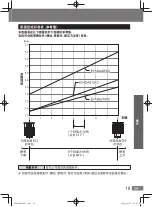
Page 19: ...N 19 0 1 2 3 4 5 6 7 8 5 0 4 5 4 0 3 5 3 0 2 5 2 0 1 5 1 0 0 5 0 0 EYADA218XC EYADA212XC EYADA407XC 1 12 12 8 96 96 0 8 EY9310ADA202 indb 19 EY9310ADA202 indb 19 2023 12 07 19 01 43 2023 12 07 19 01 4...

Page 20: ...CN 20 F R R F ON OFF P 17 OK P 35 P 39 OK EY9310ADA202 indb 20 EY9310ADA202 indb 20 2023 12 07 19 01 43 2023 12 07 19 01 43...

Page 21: ...CN 21 OK P 25 P 39 P 39 P 40 OK OK OK NG NOK OK P 40 NG EY9310ADA202 indb 21 EY9310ADA202 indb 21 2023 12 07 19 01 44 2023 12 07 19 01 44...

Page 22: ...CN 22 1 2 OK OK OK 2 OK 3 F R EY9310ADA202 indb 22 EY9310ADA202 indb 22 2023 12 07 19 01 44 2023 12 07 19 01 44...

Page 23: ...CN 23 c u c 25 26 27 28 29 30 31 b 41 41 42 43 u 32 33 34 35 36 37 38 n 39 39 40 40 EY9310ADA202 indb 23 EY9310ADA202 indb 23 2023 12 07 19 01 44 2023 12 07 19 01 44...

Page 24: ...CN 24 b4 1 P 43 OK P 22 OK OK EY9310ADA202 indb 24 EY9310ADA202 indb 24 2023 12 07 19 01 44 2023 12 07 19 01 44...

Page 25: ...CN 25 c c1 OK P 20 21 1 OK 2 OK 3 OK 3 OK P 22 c1 OK OFF 1 99 OK OK P 22 EY9310ADA202 indb 25 EY9310ADA202 indb 25 2023 12 07 19 01 45 2023 12 07 19 01 45...

Page 26: ...CN 26 c c2 1 2 3 2 OK P 22 c2 OK 1 0 0 OK OK P 22 EY9310ADA202 indb 26 EY9310ADA202 indb 26 2023 12 07 19 01 45 2023 12 07 19 01 45...

Page 27: ...CN 27 c3 OK 1 2 1 1 2 OK P 22 c3 OK 1 OFF 1 1 c7 P 31 OK OK P 22 EY9310ADA202 indb 27 EY9310ADA202 indb 27 2023 12 07 19 01 45 2023 12 07 19 01 45...

Page 28: ...CN 28 c c4 1 1 3 1 OK P 22 c4 OK 1 OK OK P 22 EY9310ADA202 indb 28 EY9310ADA202 indb 28 2023 12 07 19 01 45 2023 12 07 19 01 45...

Page 29: ...CN 29 c5 0 3 0 3 0 3 OK P 22 c5 OK OFF 0 1 9 9 OK OK P 22 EY9310ADA202 indb 29 EY9310ADA202 indb 29 2023 12 07 19 01 46 2023 12 07 19 01 46...

Page 30: ...CN 30 c c6 OK OK c6 u6 u6 P 37 OK OK OK P 22 c6 OK OFF 0 1 9 9 OK OK P 22 EY9310ADA202 indb 30 EY9310ADA202 indb 30 2023 12 07 19 01 46 2023 12 07 19 01 46...

Page 31: ...CN 31 c7 OK 3 0 3 0 OK 3 0 OK P 22 c7 OK OFF 0 1 9 9 OK OK P 22 EY9310ADA202 indb 31 EY9310ADA202 indb 31 2023 12 07 19 01 46 2023 12 07 19 01 46...

Page 32: ...CN 32 u u1 u2 u3 P 33 34 OK OK P 22 u1 OK OFF 0 1 9 9 OK OFF 0 1 9 9 OK u2 u3 7 OK P 22 EY9310ADA202 indb 32 EY9310ADA202 indb 32 2023 12 07 19 01 46 2023 12 07 19 01 46...

Page 33: ...50 900 1050 EYADA212XC 300 400 500 600 700 EYADA407XC 160 220 270 330 380 25 50 Level6 Level7 Level8 Level9 Level10 EYADA218XC 1200 1350 1500 1650 1800 EYADA212XC 800 900 1000 1100 1200 EYADA407XC 430...

Page 34: ...750 900 1050 EYADA212XC 300 400 500 600 700 EYADA407XC 160 220 270 330 380 25 50 Level6 Level7 Level8 Level9 Level10 EYADA218XC 1200 1350 1500 1650 1800 EYADA212XC 800 900 1000 1100 1200 EYADA407XC 43...

Page 35: ...u4 OK u7 P 38 0 3 0 6 0 3 0 6 OK 0 1 NG NOK 0 5 OK 0 8 NG NOK OK P 22 u4 OK Min OFF 0 1 9 9 OK Max OFF 0 1 9 9 OK 7 OK P 22 EY9310ADA202 indb 35 EY9310ADA202 indb 35 2023 12 07 19 01 47 2023 12 07 19...

Page 36: ...CN 36 u u5 u4 P 35 1 u4 0 6 0 6 0 6 0 0 OK P 22 u5 OK OFF ON OK u4 OK P 22 EY9310ADA202 indb 36 EY9310ADA202 indb 36 2023 12 07 19 01 47 2023 12 07 19 01 47...

Page 37: ...CN 37 u6 OK c6 u6 u6 P 30 OK OK OK P 22 u6 OK 0 5 0 5 9 9 OK OK P 22 EY9310ADA202 indb 37 EY9310ADA202 indb 37 2023 12 07 19 01 47 2023 12 07 19 01 47...

Page 38: ...CN 38 u u7 0 5 OK OK P 22 u7 OK OFF ON OK OK P 22 EY9310ADA202 indb 38 EY9310ADA202 indb 38 2023 12 07 19 01 48 2023 12 07 19 01 48...

Page 39: ...CN 39 n n1 OK P 22 n1 OK 1 OFF OK OK OK OK P 22 n2 OK P 22 n2 OK 1 1 3 OK OK P 22 EY9310ADA202 indb 39 EY9310ADA202 indb 39 2023 12 07 19 01 48 2023 12 07 19 01 48...

Page 40: ...CN 40 n n3 NG NOK OK P 22 n3 OK 1 OFF NG NOK NG NOK OK OK P 22 n4 OK OK P 22 n4 OK 2 OFF OK OK P 22 EY9310ADA202 indb 40 EY9310ADA202 indb 40 2023 12 07 19 01 48 2023 12 07 19 01 48...

Page 41: ...CN 41 b b1 OK P 22 b1 OK 1 OFF ON OK OK P 22 b2 NG NOK P 45 OK P 22 b2 OK 1 NG NOK OK OK P 22 EY9310ADA202 indb 41 EY9310ADA202 indb 41 2023 12 07 19 01 48 2023 12 07 19 01 48...

Page 42: ...CN 42 b b3 P 44 OK P 22 b3 OK OFF ON ON OK OK P 22 EY9310ADA202 indb 42 EY9310ADA202 indb 42 2023 12 07 19 01 49 2023 12 07 19 01 49...

Page 43: ...CN 43 b4 1 OK P 24 1 OK P 22 b4 OK 1 OK OK OK P 22 EY9310ADA202 indb 43 EY9310ADA202 indb 43 2023 12 07 19 01 49 2023 12 07 19 01 49...

Page 44: ...CN 44 PLC OFF EY9310ADA202 indb 44 EY9310ADA202 indb 44 2023 12 07 19 01 49 2023 12 07 19 01 49...

Page 45: ...CN 45 OK OK 0 5 NG NOK NG NOK 0 5 0 5 b3 1 2 ON P 42 COM NG NOK b2 P 41 EY9310ADA202 indb 45 EY9310ADA202 indb 45 2023 12 07 19 01 49 2023 12 07 19 01 49...

Page 46: ...N 46 N 1 2 N 1 2 2 1 ON OFF ON OFF 0 5 ON OFF PLC ON ON OFF 0 5 NG NOK ON OFF 0 5 0 5 OK ON OFF NG NOK b2 P 41 c7 P 31 EY9310ADA202 indb 46 EY9310ADA202 indb 46 2023 12 07 19 01 49 2023 12 07 19 01 49...

Page 47: ...CN 47 OK NG NOK COM PLC 24 V 4 7 k EY9310ADA202 indb 47 EY9310ADA202 indb 47 2023 12 07 19 01 49 2023 12 07 19 01 49...

Page 48: ...CN 48 DC24 V 10 5 mA DC24 V 10 20 mA 30 V 20 mA PLC COM OFF EY9310ADA202 indb 48 EY9310ADA202 indb 48 2023 12 07 19 01 49 2023 12 07 19 01 49...

Page 49: ...M5 0 3 N m 2 5 N m 0 3 N m 2 0 N m 1 5 N m 4 4 N m 96 10 1200 10 1800 10 650 10 AC100 240 V 50 60 Hz DC30 V 6 35 mm 9 mm 13 mm 12 mm 17 5 mm 271mm 38 mm 630 g 1 OK NG NOK 7 OK 5 3 EY9310ADA202 indb 49...

Page 50: ...AC100 240 V 50 60 Hz 2 6 A DC30 V 3 A 0 16 W 100 V 0 21 W 240 V 590 g 177 mm 44 mm 76 mm 1 m PLC ON OFF 2 m EYADA407XC 2 m 3 m 3 m EY9310ADA202 indb 50 EY9310ADA202 indb 50 2023 12 07 19 01 49 2023 1...

Page 51: ...CN 51 EY9310ADA202 indb 51 EY9310ADA202 indb 51 2023 12 07 19 01 49 2023 12 07 19 01 49...

Page 52: ...CN 52 E0 E7 OK EE F2 Fb OK P 54 EY9310ADA202 indb 52 EY9310ADA202 indb 52 2023 12 07 19 01 50 2023 12 07 19 01 50...

Page 53: ...CN 53 P 35 EY9310ADA202 indb 53 EY9310ADA202 indb 53 2023 12 07 19 01 50 2023 12 07 19 01 50...

Page 54: ...u2 P 33 01 Level 1 25 02 u3 P 34 01 Level 1 25 02 u4 2 P 35 OFF 0 1 0 1 0 2 u5 P 36 OFF 1 ON u6 P 37 0 5 0 5 0 6 0 6 0 7 u7 P 38 OFF 1 ON n notification n1 P 39 OFF 1 OK 2 n2 P 39 1 1 2 n3 P 40 OFF 1...

Page 55: ...9 9 9 9 0 2 0 2 9 9 9 9 0 2 0 2 9 9 9 9 5 02 Level 2 33 10 Level 10 5 02 Level 2 33 10 Level 10 0 2 0 2 9 9 9 9 0 7 0 7 9 9 9 9 2 OK 2 3 2 NG NOK 2 3 2 NG NOK 2 ON EY9310ADA202 indb 55 EY9310ADA202 in...

Page 56: ...14 36 17 C 38 14 24 D 26 12 16 F 13 20 G 26 H PLC 44 J 21 31 NG NOK 21 OK 20 OK 30 OK 37 OK 27 32 33 K 13 L 17 16 12 16 M 38 Q 20 17 22 EY9310ADA202 indb 56 EY9310ADA202 indb 56 2023 12 07 19 01 50 20...

Page 57: ...CN 57 R 32 32 S 40 39 40 18 25 39 33 34 42 41 13 28 T 35 12 X 43 41 Y 29 Z 32 34 26 13 20 EY9310ADA202 indb 57 EY9310ADA202 indb 57 2023 12 07 19 01 50 2023 12 07 19 01 50...

Page 58: ...E SJ T11364 GB T 26572 GB T 26572 GB T 3883 1 2014 GB T 3883 202 2019 GB 4343 1 2018 GB 17625 1 2012 GB 4943 1 2022 GB T 9254 1 2021 GB 17625 1 2012 EY9310ADA202 indb 58 EY9310ADA202 indb 58 2023 12 0...

Page 59: ...n NUMBER 39 BASIC SETTING MENU b NUMBER 41 HOW TO USE COMMUNICATION CABLE 44 OPERATION CAPACITY AND SPECIFICATIONS 49 CLEANING AND STORAGE 51 ERROR CODES 52 SETTING MODE LIST 54 INDEX 56 OTHERS IMPORT...

Page 60: ...aving screws unfastened P 25 Set the number of screws to fasten To check the fastening status P 20 21 Set the detection lamp To perform fastening quality judgement P 35 Set the upper and lower limits...

Page 61: ...unexpected momentary rotations when performing judgement Ignore Judgement Time Setting 29 Slow the rotation rate at the start to prevent galling etc Soft Start Setting 32 Slow the rotation rate befor...

Page 62: ...is not operating When replacing a bit or accessories or when storing the tool always set the forward reverse lever to the trigger switch lock position and disconnect the power cord Failure to observe...

Page 63: ...in injury Following the Operating Instructions attach a bit or other pointed tools and accessories securely Failure to securely attach them may cause detachment resulting in injury Before use remove a...

Page 64: ...ailure to observe this may cause injury Do not use the tool with oil or other foreign material attached to it Otherwise an accident may occur if the tool falls Also such oil or other foreign material...

Page 65: ...the tool Do not disassemble or repair the tool Doing so may cause fire electric shock or injury For repair consult your dealer or our customer support team Keep dry Avoid the following use of tools Do...

Page 66: ...environment and use common sense during work Failure to observe this may cause an accident or injury When installing the power adapter on a wall securely screw it to prevent it from falling Otherwise...

Page 67: ...t use the tool when you are tired Failure to observe this may cause an accident or injury Do not allow a child or any other person who is not an operator to come near the workplace or touch the tool D...

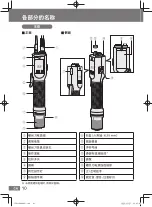
Page 68: ...tch handle Bit holder for hex shaft 6 35 mm Clutch cover Serial plate Communication cable connector Cap Screwdriver cord connector Forward Reverse lever Rating warning and caution indications Front Vi...

Page 69: ...11 BEFORE USE PREPARATION OPERATION OTHERS EN Display OK button button button Operation panel EY9310ADA202 indb 11 EY9310ADA202 indb 11 2023 12 07 19 01 53 2023 12 07 19 01 53...

Page 70: ...Attachment Supplied for EYADA407XC only Power Adapter EYSZP001 Grip Attachment EYSXA102 For information about the components see P 15 For China only Power Cord 1 m For Malaysia only Power Cord 1 m For...

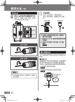
Page 71: ...he position to lock the trigger switch NOTE If the forward reverse lever is switched while the motor is in action the motor is forcibly stopped to rotate Attaching Screwdriver Hanger Pull the screwdri...

Page 72: ...come off by pulling it lightly Bits That Can Be Attached to This Unit 6 35 mm Ball groove section Centre Straight bits without a ball groove section cannot be used Length of A Double ended bit 12 mm t...

Page 73: ...When attaching or removing the grip attachment set the forward reverse lever to the Trigger switch locked position and turn OFF the power switch of the power adapter P 13 16 Remove the bit before att...

Page 74: ...ect the screwdriver cord to the power adapter and this unit Check the orientation of the connector and attach it correctly Fix it with a joint ring Power adapter sold separately Joint ring Joint ring...

Page 75: ...the lever Rotation stops when you release the lever Pull the lever Switching to Push Start Mode Set the forward reverse lever to the position The trigger switch gets locked P 13 Press the bit end aga...

Page 76: ...rque according to the recommended fastening torque chart P 19 Do not use the tool in such a manner that causes the motor to lock Attach the clutch cover Turn the clutch cover clockwise Securing ring A...

Page 77: ...als and fixing methods Measurement conditions Based on our specified measurement conditions In actual work they vary depending on the surrounding conditions such as screws materials and fixing methods...

Page 78: ...t is not a failure In case of quick ON OFF the rotation startup will be late a little for that You can select lever start or push start for start mode P 17 Checking Fastening Status This unit notifies...

Page 79: ...number of screws has been fastened successfully Set the count quantity P 25 The lighting colour of the lamp can be changed in the menu P 39 The buzzer pattern can be changed in the menu P 39 The buzze...

Page 80: ...reverse lever to the trigger switch lock position Set it to the position Hold down the OK button A buzzer sounds short twice two short beeps and the detection lamp blinks yellow Two short beeps Blinki...

Page 81: ...rnal Output Signal Setting 41 External Input Drive Permission Setting 42 Tool Reset Permission Setting 43 Utility Menu u Number Display Description Reference page Soft Start Soft Snug Time Setting 32...

Page 82: ...ng Procedure Switch to setting mode Set the forward reverse lever to the trigger switch lock position and hold down the OK button For details see P 22 Hold down the OK button button and button at the...

Page 83: ...ep 1st screw Fastening OK 2nd screw Fastening OK 3rd screw Fastening OK When it is set to 3 Setting Procedure Switch to setting mode Set the forward reverse lever to the trigger switch lock position a...

Page 84: ...value appears on the display Select a desired one by pressing the and buttons The default is _1 Display Count method Count down The number of fastened screws is counted from the set value down to 0 C...

Page 85: ...ons The default is _1 Display Count return OFF Reverse rotations are not counted Return 1 count The count is put back by reverse rotations Return to start The count is reset by reverse rotations In a...

Page 86: ...r switch lock position and hold down the OK button P 22 Choose c4 by pressing the and buttons and press the OK button A set value appears on the display Select a desired one by pressing the and button...

Page 87: ...rocedure Switch to setting mode Set the forward reverse lever to the trigger switch lock position and hold down the OK button P 22 Choose c5 by pressing the and buttons and press the OK button A set v...

Page 88: ...the time to ignore counting even if they are fastened again Count ignored Fastening OK Fastening is executed during the set time Setting Procedure Switch to setting mode Set the forward reverse lever...

Page 89: ...up will occur for 3 0 s allowing you to reverse rotations to redo or loosen screws Setting Procedure Switch to setting mode Set the forward reverse lever to the trigger switch lock position and hold...

Page 90: ...rse lever to the trigger switch lock position and hold down the OK button P 22 Choose u1 by pressing the and buttons and press the OK button A set value appears on the display Select a desired one by...

Page 91: ...s on the display Select a desired one by pressing the and buttons The default is 10 Press the OK button to confirm it When the setting is completed a buzzer sounds long a long beep and the display ret...

Page 92: ...display Select a desired one by pressing the and buttons The default is 10 Press the OK button to confirm it When the setting is completed a buzzer sounds long a long beep and the display returns to t...

Page 93: ...ch lock position and hold down the OK button P 22 Choose u4 by pressing the and buttons and press the OK button A set value appears on the display Select a desired one by pressing the and buttons The...

Page 94: ...6 in u4 Rotation Time based Detection Setting Rotation stops when the rotation time before snugging reaches 0 6 s 0 6 s 0 0 s Rotation stop Screw fastening start Setting Procedure Switch to setting m...

Page 95: ...ate Fastening OK Fastening is executed during the set time Setting Procedure Switch to setting mode Set the forward reverse lever to the trigger switch lock position and hold down the OK button P 22 C...

Page 96: ...s the maximum value of rotation time button Displays the minimum value of rotation time OK button Redisplays the latest measured data button held down Resets the maximum and minimum values button held...

Page 97: ...mpleted a buzzer sounds long a long beep and the display returns to the menu screen Back to Operation Mode Hold down the OK button P 22 n2 Buzzer Pattern Setting You can set the buzzer pattern for cou...

Page 98: ...ong beep and the display returns to the menu screen Back to Operation Mode Hold down the OK button P 22 n4 Buzzer Volume Setting You can set the buzzer volume This is a common setting for the confirma...

Page 99: ...eted a buzzer sounds long a long beep and the display returns to the menu screen Back to Operation Mode Hold down the OK button P 22 b2 External Output Signal Setting You can select Count up signal or...

Page 100: ...use an improper Electric Screwdriver it will not start and its detection lamp will blink red with a buzzer Blinking red Not blinking Buzz When drive permission is not given Setting Procedure Switch t...

Page 101: ...n the OK button P 22 Choose b4 by pressing the and buttons and press the OK button A set value appears on the display Select a desired one by pressing the and buttons The default is _1 Display Tool re...

Page 102: ...r adapter Attaching Communication Cable Remove the connector cap Connector cap Check the orientation of the connector and attach it firmly as far as it will go Tie the cables in a bundle to prevent th...

Page 103: ...n a motor forward state Purple Output Motor reverse signal Output continues in a motor reverse state Green Input Drive permission signal When _1 or _2 is set through b3 External Input Drive Permission...

Page 104: ...Screwdriver starts and allows work only while an ON signal is being input from an external device PLC Permission is given only to the tools to use The tools that should not be used are not given permi...

Page 105: ...al Blue Fastening NG NOK signal Count up signal Yellow Motor forward signal Purple Motor reverse signal Green Drive permission signal Light blue COM Inside of tool Inside of PLC External power supply...

Page 106: ...er supply to the signal output wire without using a current limiting resistor Doing so breaks the photocoupler Do not directly connect a relay motor lamp or any other device to the signal output wire...

Page 107: ...k them with actual work before use Tool Specifications Power Supply Power supplied by power adapter sold separately 100 to 240 V AC 50 60 Hz Motor Brushless motor 30 V DC Bit Holder One touch bit lock...

Page 108: ...tems Screwdriver cord 2 m Screwdriver hanger Clutch cover Grip attachment Supplied for EYADA407XC only Separately Sold Items Screwdriver cord 2 m 3 m Screwdriver hanger Clutch cover Grip attachment Co...

Page 109: ...ducting Periodic Inspection Periodically inspect for any loose screws damage or abnormal operation Periodically inspect the power adapter for any signs of damage Storage Avoid the following conditions...

Page 110: ...The internal protective sensor is out of order Send the tool for repair The tool is overloaded or the motor is out of order for example Eliminate the condition s that caused the overload and recheck t...

Page 111: ...erse lever during a fastening process During a fastening process the tool was overloaded or the motor failed Eliminate the condition s that caused the overload and recheck the condition When this does...

Page 112: ...Setting P 36 OFF 1 ON u6 Disable Fastening Time Setting P 37 0 5 0 5 s 0 6 0 6 s 0 7 u7 Stopwatch Mode P 38 OFF 1 ON n series notification Settings related to notification lamp and buzzer n1 Lamp Ligh...

Page 113: ...vel 10 Maximum speed um 02 Level 2 About 33 of maximum 10 Level 10 Maximum speed 0 2 0 2 s 9 9 9 9 s 0 7 0 7 s 9 9 9 9 s Blue 2 Fastening OK Blue Count up Count complete Green 2 Three short beeps d re...

Page 114: ...Settings 24 L Lever Start Mode 17 M Making Rotation Stop Automatically after Set Time Has Passed 36 Manually Resetting Count 28 Measuring Rotation Time of Screw Fastening 38 P Permitting Tool Reset 4...

Page 115: ...ber of Screws to Fasten 25 Setting Screws Not to Be Counted If Fastened Again after Fastening OK 30 Setting Speed of Soft Snug 34 Setting Speed of Soft Start 33 Setting the Tool Not to Start during th...

Page 116: ...58 MEMO EY9310ADA202 indb 58 EY9310ADA202 indb 58 2023 12 07 19 02 04 2023 12 07 19 02 04...

Page 117: ...59 MEMO EY9310ADA202 indb 59 EY9310ADA202 indb 59 2023 12 07 19 02 04 2023 12 07 19 02 04...

Page 118: ...60 MEMO EY9310ADA202 indb 60 EY9310ADA202 indb 60 2023 12 07 19 02 04 2023 12 07 19 02 04...

Page 119: ...ll free number https www panasonic com in corporate e waste management html Do s Don ts No Do s Don ts 1 All electrical and electronic products are required to be handed over only to the Authorized re...

Page 120: ...023 12 258 Panasonic 4008 209 376 Panasonic Corporation https panasonic cn 1006 Oaza Kadoma Kadoma shi Osaka 571 8501 Japan https www panasonic com EY9310ADA202 indb 62 EY9310ADA202 indb 62 2023 12 07...

Reviews: