3DQDVRQLF
45
17.5. Colour Decoder
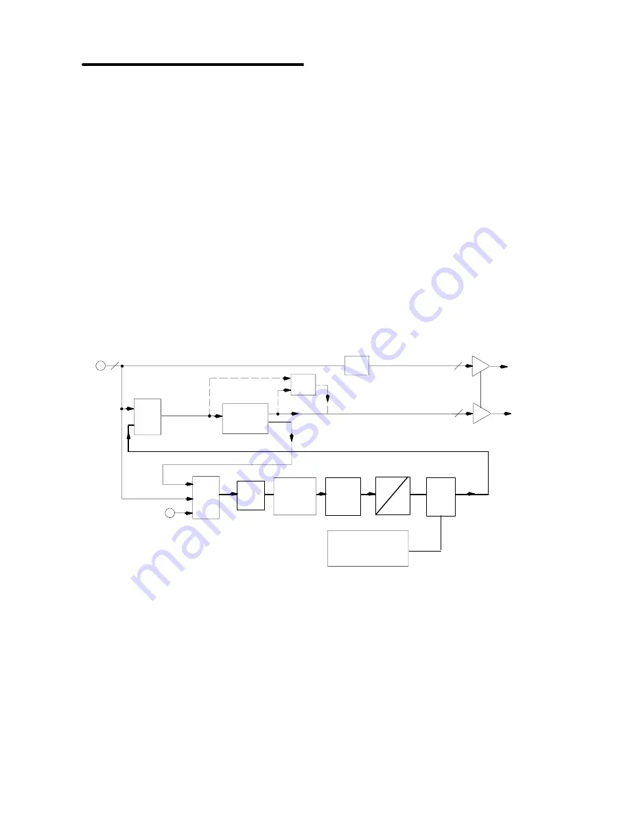
In the colour decoder stage the standard luminance
and
chrominance separation and multi-standard
colour demodulation is carried out. The colour
demodulation uses an asynchronous clock, thus
allowing
a
unified
architecture
for
all
colour
standards.
The colour decoder also provides some special
modes such as wide band chroma format which is
intended for S-VHS wide bandwidth chroma.
If the adaptive comb filter of the VDP3120
IC601
is
used for luminance chrominance separation, the
colour decoder uses the S-VHS processing mode.
The output of the colour decoder is YC
r
C
b
in a 4:2:2
format.
17.5.1.Digitised Composite Video Processing
The video signal which is fed to the colour decoder
section as 8 bits of information is split into 2 paths .
1.
Luminance Processing
2.
Chrominance Processing
17.5.2.Luminance Processing
The
composite
video
signal
is
fed
to
a
programmable notch filter which filters out the colour
information.
The position of the filter centre frequency depends
on the sub-carrier frequency for PAL/NTSC.
For SECAM, the notch filter is directly controlled by
the chroma carrier frequency
From the output of the notch filter the luminance
signal is fed to the Scaler stage.
I.F.
Comp.
Mixer
Quadrature
Down
Sampling
LPF
Bell
Filter
Burst
Det.
APC /
Colour Killer
ACC Stage
Standard Recognition
Mux
1
Mux
2
1H Delay
Chroma
CVBS / Y
8
8
8
digital
Y
Cr Cb
digital
Cross
Switch
Notch
Filter
Summary of Contents for EURO 4 Chassis
Page 24: ...3DQDVRQLF 24 ...
Page 26: ...3DQDVRQLF 26 TV STANDARDS ...
Page 93: ...3DQDVRQLF 10 ...
Page 97: ...3DQDVRQLF 14 Chapter 2 EURO 4 Supplement P Board DAF Circuit ...
Page 101: ...3DQDVRQLF 18 ...
Page 121: ...3DQDVRQLF 38 Chapter 3 EURO 4H Supplement Y Board Schematic ...
Page 124: ...3DQDVRQLF 41 ...


