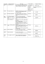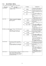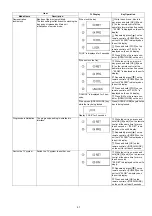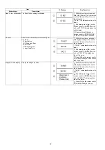
28
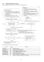
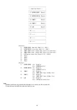
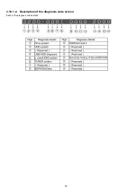
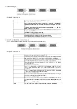
3. USB-HDD Diagnosis
<Diagnosis Result Value>
4. Digital/Tuner/Main P.C.B. System Diagnosis
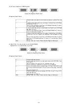
(1) IC communication in the digital P.C.B. (CPU and Flash/DDR/HDMI, etc.)
<Diagnosis Result Value>
0
No abnormality was detected from USB-HDD inspection.
Please check other diagnosis items.
1
No USB-HDD is connected or some other device is connected. Check to see if
there is any problem with the USB cable connection or the voltage power sup-
ply.
If there is no problem with the supply voltage or connection, there is a high pos-
sibility of USB-HDD unit defect.
2
An abnormality that can be determined as USB-HDD failure was detected.
Replace the USB-HDD unit.
6
If multiple USB-HDD units are connected.
7
If an unsupported USB-HDD is connected.
8
Unable to execute the Diagnosis Code Function normally.
There is a possibility of malfunction in the digital P.C.B. side.
0
No abnormality was detected in the digital P.C.B..
1
If there is a communication failure between CPU and FLASH/DDR, there is a
high possibility of digital P.C.B. circuit (such as foil cutting) or parts failure.
2
If there is a communication failure between CPU and HDMI-LSI, there is a high
possibility of digital P.C.B. circuit (such as foil cutting) or parts failure.
3
There is a communication failure between CPU and FLASH/DDR, and between
CPU and HDMI-LSI.
Take measures for "1" and "2".
4
There is an abnormality in HDMI-CEC circuit operation (High/Low Output).
There is a high possibility of digital P.C.B. circuit failure (such as foil cutting) or
parts failure.
5
There is a communication failure between CPU and FLASH/DDR, abnormality
in HDMI-CEC circuit operation (High/Low Output).
Take measures for "1" and "4".
6
There is a communication failure between CPU and HDMI-LSI, abnormality in
HDMI-CEC circuit operation (High/Low Output).
Take measures for "2" and "4".
7
There is a communication failure between CPU and FLASH/DDR and between
CPU and HDMI-LSI, abnormality in HDMI-CEC circuit operation (High/Low Out-
put).
Take measures for "3" and "4".
Other
The Input Code is not correct. Please check the Diagnosis Code again.
Summary of Contents for DMR-PWT550GL
Page 2: ...2 ...
Page 3: ...3 ...
Page 26: ...26 3 10 1 2 Description of the diagnosis code screen Each of the diagnosis code details ...
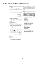
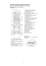
Page 33: ...33 5 Location of Controls and Components ...
Page 34: ...34 ...
Page 35: ...35 ...
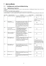
Page 50: ...50 Item FL Display Key Operation Mode Name Description Remote controller key ...
Page 67: ...67 9 11 6 Grease ...
Page 71: ...71 10 1 2 Checking and Repairing of BD Drive ...
Page 72: ...72 10 1 3 Checking and Repairing of Main P C B ...
Page 73: ...73 10 1 4 Checking and Repairing of Digital P C B ...
Page 74: ...74 ...
Page 83: ...Model No DMR PWT550GL GZ SCHEMATIC DIAGRAM NOTICE ...
Page 84: ...Model No DMR PWT550GL GZ PART LIST NOTICE ...
Page 85: ...Model No DMR PWT550GL GZ ABBREVIATION ...
Page 86: ...Model No DMR PWT550GL GZ POWER SECTION POWER P C B ...
Page 87: ...Model No DMR PWT550GL GZ MAIN NET SECTION MAIN P C B ...
Page 88: ...Model No DMR PWT550GL GZ FRONT SW SECTION MAIN P C B ...
Page 89: ...Model No DMR PWT550GL GZ SATA DIGITAL P C B ...
Page 90: ...Model No DMR PWT550GL GZ AUDIO IO SECTION DIGITAL P C B ...
Page 91: ...Model No DMR PWT550GL GZ DDR3 CH 0 SECTION DIGITAL P C B ...
Page 92: ...Model No DMR PWT550GL GZ DDR3 CH 1 SECTION DIGITAL P C B ...
Page 93: ...Model No DMR PWT550GL GZ DEMOD SECTION DEMOD P C B ...
Page 94: ...Model No DMR PWT550GL GZ DIGI NET SECTION DIGITAL P C B ...
Page 95: ...Model No DMR PWT550GL GZ DIGITAL POWER SECTION DIGITAL P C B ...
Page 96: ...Model No DMR PWT550GL GZ ETHER SECTION DIGITAL P C B ...
Page 97: ...Model No DMR PWT550GL GZ EXBUS PERI SECTION DIGITAL P C B ...
Page 98: ...Model No DMR PWT550GL GZ PEAKS PRO4 SECTION DIGITAL P C B ...
Page 99: ...Model No DMR PWT550GL GZ PRO4 POWER SECTION DIGITAL P C B ...
Page 100: ...Model No DMR PWT550GL GZ SATA SD USB SECTION DIGITAL P C B ...
Page 101: ...Model No DMR PWT550GL GZ TIMER SECTION DIGITAL P C B ...
Page 102: ...Model No DMR PWT550GL GZ VIDEO HDMI SECTION DIGITAL P C B ...
Page 103: ...Model No DMR PWT550GL GZ MAIN P C B COMPONENT SIDE ...
Page 104: ...Model No DMR PWT550GL GZ MAIN P C B FOIL SIDE ...
Page 105: ...Model No DMR PWT550GL GZ DIGITAL P C B COMPONENT SIDE ...
Page 106: ...Model No DMR PWT550GL GZ DIGITAL P C B FOIL SIDE ...
Page 107: ...Model No DMR PWT550GL GZ FRONT SW P C B COMPONENT SIDE ...
Page 108: ...Model No DMR PWT550GL GZ FRONT SW P C B FOIL SIDE ...
Page 109: ...Model No DMR PWT550GL GZ SATA P C B COMPONENT SIDE ...
Page 110: ...Model No DMR PWT550GL GZ SATA P C B FOIL SIDE ...
Page 122: ...Model No DMR PWT550GL GZ Exploded View ...
Page 123: ...Model No DMR PWT550GL GZ Mechanism View ...

