background image

15

3.5.

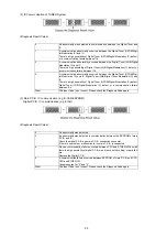
Micro Fuse conducting check

This unit uses the Micro Fuse.
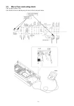
Check the Micro Fuse conducting using the Tester at the check points below.

Summary of Contents for DMR-PWT550GL

Page 1: ...Panasonic Corporation 2015 Unauthorized copying and distribution is a violation of law Order No CHM1504013CE Blu ray Disc Player HDD Recorder Model No DMR PWT550GL DMR PWT550GZ Colour K Black Type ...

Page 2: ...2 ...

Page 3: ...3 ...

Page 4: ... Specifications 31 5 Location of Controls and Components 33 6 Installation Instructions 36 6 1 Taking out the Disc from BD Drive Unit when the Disc cannot be ejected by OPEN CLOSE button 36 7 Service Mode 37 7 1 Self Diagnosis and Special Mode Setting 37 8 Service Fixture Tools 57 9 Disassembly and Assembly Instructions 58 9 1 Disassembly flow chart 58 9 2 P C B Positions 58 9 3 Top Case 59 9 4 Fr...

Page 5: ... the exposed metal does not have a return path to the chassis the reading must be 1 1 2 Leakage Current Hot Check See Figure 1 1 Plug the AC cord directly into the AC outlet Do not use an isolation transformer for this check 2 Connect a 1 5kΩ 10 watts resistor in parallel with a 0 15μF capacitors between each exposed metallic part on the set and a good earth ground such as a water pipe as shown in...

Page 6: ...ure of the assembly 3 Use only a grounded tip soldering iron to solder or unsolder ES devices 4 Use only an anti static solder remover device Some solder removal devices not classified as anti static ESD protected can generate electrical charge sufficient to damage ES devices 5 Do not use freon propelled chemicals These can generate electrical charges sufficient to damage ES devices 6 Do not remov...

Page 7: ... not look at the focus lens using optical instruments 4 Recommend not to look at pickup lens for a long time ACHTUNG Dieses Produkt enthält eine Laserdiode Im eingeschalteten Zustand wird unsichtbare Laserstrahlung von der Laserein heit abgestrahlt Wellenlänge 661 nm DVDs 783 nm CDs 405nm BDs Maximale Strahlungsleistung der Lasereinheit 100 μW VDE Die Strahlungan der Lasereinheit ungefährlich wenn...

Page 8: ...is used Definition The letter of PbF is printed on the PCB using the lead free solder To put lead free solder it should be well molten and mixed with the original lead free solder Remove the remaining lead free solder on the PCB cleanly for soldering of the new IC Since the melting point of the lead free solder is higher than that of the normal lead solder it takes the longer time to melt the lead...

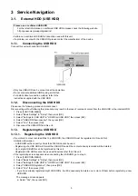
Page 9: ...s for USB HDD in HDD Disc USB HDD then press OK 4 Select USB HDD Disconnection then press OK 5 Select Yes then press OK 6 Disconnect the USB HDD from this unit 3 1 3 Registering the USB HDD 3 1 3 1 Registering the USB HDD If you intend to move recorded titles to a USB HDD the USB HDD must be registered to this unit first Limitation information A USB HDD with a capacity of less than 160 GB cannot b...

Page 10: ...ECT NAVIGATOR Cancellation of all USB HDD Registrations This function cancells the registrations of all the USB HDDs registered on this unit Only do this if you are going to dispose of this unit Before operation perform 3 1 2 Disconnecting the USB HDD and remove the USB HDD It is not possible to play back the content from a USB HDD whose registration has been cancelled 1 Press FUNCTION MENU 2 Sele...

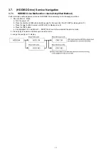
Page 11: ...ed When the cable USB cable between the main unit and the USB HDD is poorly connected cable disconnection etc Abnormal operation 2 When a wrong USB HDD incompatible with this unit is connected Connected USB device cannot be used with this unit etc will be automatically displayed Incompatible USB HDD When devices with capacity of less than 160GB or more than 2TB or other USB devices are connected A...

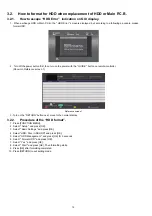
Page 12: ...on on remote controller Shown in Reference screen 1 Reference screen 1 3 Turn on the RETURN button next move to the normal display 3 2 2 Procedure of the HDD format 1 Press FUNCTION MENU 2 Select Setup and press OK 3 Select Basic Settings and press OK 4 Select HDD Disc USB HDD and press OK 5 Select HDD Management and press OK for 3 seconds 6 Select Format HDD and press OK 7 Select Yes and press OK...

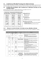
Page 13: ...sure to use the supplied remote control 3 4 Entering Special Modes with Combination of Multiple Pressing on the Remote Control Enter the following special modes by multiple pressing functions on the supplied remote control After entering each mode switch to the desired menus for operation 3 4 1 Disclosure mode Combination of multiple pressing OK Blue Yellow Press and hold OK Blue Yellow on the rem...

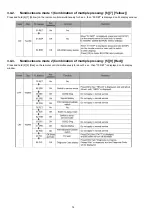
Page 14: ... 7 Yellow on the remote control simultaneously for 5 sec then 50 RET is displayed on FL display window 3 4 3 Nondisclosure mode 2 Combination of multiple pressing 5 9 Red Press and hold 5 9 Red on the remote control simultaneously for about 5 sec then 70 RET is displayed on FL display window ...

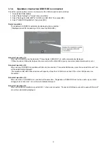
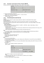
Page 15: ...15 3 5 Micro Fuse conducting check This unit uses the Micro Fuse Check the Micro Fuse conducting using the Tester at the check points below ...

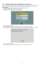
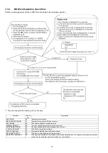
Page 16: ...ed when the USB connection is made to a digital camera etc Example below When JPEG materials have been recorded Displayed items differ depending on the recorded contents Abnormal operation Example 1 Warning is displayed automatically if overcurrent is detected when a USB device is connected When a USB device or this unitís USB terminal shorts out or the power supply type of USB device is connected...

Page 17: ... 1 Execute Service Mode a Turn the power off b Press the 5 9 and R button simultaneously for five seconds then 70 RET is displayed on FL c Press the button to select until 80 SRV is displayed on FL d Press the OK button e It is displayed on FL as HELLO SERV It is shown to have entered the service mode 2 Press 3 8 of remote controller keys in service mode 3 Judge the quality on FL display ...

Page 18: ...ve is unable to access the disc MEDIUM ERROR 03 An error caused by medium error has occurred HARDWARE ERROR 04 An error caused by the drive hardware has occurred ILLEGAL REQUEST 05 The CDB or parameter is illegal UNIT ATTENTION 06 The drive is alerting the host to some event DATA PROTECTED 07 The disc is read protected or write protected ABORTED COMMAND 0B The drive has aborted an I O process or c...

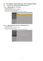
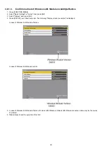
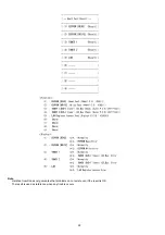
Page 19: ...up then press OK 3 Select Network Settings in Network then press OK 4 Select Wireless in LAN Connection Mode 5 Press OK The following Wireless Setting screen example is displayed 3 8 1 2 Method of displaying Wireless LAN Module Version 1 Press FUNCTION MENU 2 Select Basic Settings in Setup then press OK 3 Select System Information in Others 4 Press OK The following System Information screen exampl...

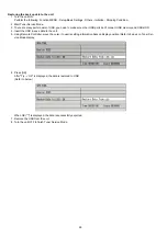
Page 20: ...and press OK 4 Press STATUS over than 5 seconds The following Display screen example is displayed In case of Wireless LAN Module effective In case of Wireless LAN Module invalid 5 In case of Wireless LAN Module effective Wireless LAN Module or Wirless LAN Module connection cable may be the source of problem 6 Please finally check the operation of the fact ...

Page 21: ...sly for five seconds then 70 RET is displayed on FL c Press the button to select until 82 TSR is displayed on FL d Press the OK button e It is shown to have entered the tuner service mode f The command is transmitted by attached remote control 2 Finishing Service Mode Method 1 After turning the unit OFF pull out the AC cord Method 2 Repeat turning ON and OFF twice P OFF P ON P OFF P ON 3 9 1 Hard ...

Page 22: ...22 Note Hard test result does not guarantee that problems do not exist even if the result is OK The result is used as reference when any trouble occurs ...

Page 23: ...iders unique information for each company broadcast mail two way commu nication list board or favorite page Status saving systems last channel except for VHF UHF drive selection status etc Note Of user setting information only items selected and set on the initial Setup display can be backed up and restored 1 Of user setting information except items selected and set on the initial Setup display Op...

Page 24: ... USB ports don t connect USB memory and USB HDD 4 Insert the USB in save data to the unit 5 Using Remote Controller move the cursor to userís setting information backup display position Refer to below on Tuner Ser vice Mode display 6 Press OK After Try OK is displayed the data is restored to USB Refer to below When OK is displayed the data is successfully exported 7 Remove the USB from the unit 8 ...

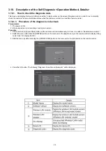
Page 25: ...code check Prerequisites 1 The power is ON 2 EE viewing screen not recording or acting as a server Procedure 1 Press and hold 5 9 and Red button on the remote control simultaneously for 5 sec to switch to Nondisclosure mode 2 2 Switch the menu with either the POWER button on the main unit or the Right cursor on the remote control to display Diag nosis Code FL display 96 DIC 3 Start the menu by eit...

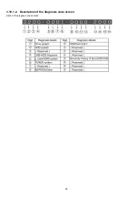
Page 26: ...26 3 10 1 2 Description of the diagnosis code screen Each of the diagnosis code details ...

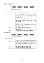
Page 27: ...r improvement If the turntable is dirty malfunction may originate from slipping phenomenon etc Please perform cleaning If the disk cannot be read written properly after cleaning replacing the Drive may be necessary 8 Unable to execute the Diagnosis Code Function normally There is a possibility of malfunction in the digital P C B side 9 There is an error that can be determined as unsupported Drive ...

Page 28: ...nication failure between CPU and FLASH DDR there is a high possibility of digital P C B circuit such as foil cutting or parts failure 2 If there is a communication failure between CPU and HDMI LSI there is a high possibility of digital P C B circuit such as foil cutting or parts failure 3 There is a communication failure between CPU and FLASH DDR and between CPU and HDMI LSI Take measures for 1 an...

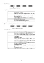
Page 29: ...OFDM Digi tal Modulation IC and IC Digital Tuner LNB Digital Tuner Modulation IC and IC There is a high possibility of Digital Tuner OFDM Digital Modulation IC defect Digital Tuner LNB Digital Modulation IC defect or a communication failure between ICs Other The Input Code is not correct Please check the Diagnosis Code again 0 No abnormality was detected 2 An abnormality was detected in communicat...

Page 30: ...of malfunction is in the digital P C B 2 If there is malfunction in HDD diagnosis items there is a possibility that the HDD itself fails ٛ Prioritize the HDD diagnosis results In addition if there is no malfunction in HDD diagnosis items there is a possibil ity that the cause of malfunction is in the digital P C B 3 There are malfunctions in Drive diagnosis items and HDD diagnosis items Take measu...

Page 31: ...o hazardous radiation is emitted with the safety protection Region Code DVD 4 BD Region B Playable discs BD Video Blu ray 3D BD LIVE BD ROM Version 2 4 DVD VIDEO DVD Video format CD DA Audio CD BD RE Based on Ver 2 1 other files 3 BD RE DL Based on Ver 2 1 other files 3 BD R Based on Ver 1 3 and LTH type Ver 1 3 other files 3 BD R DL Based on Ver 1 3 other files 3 DVD R DVD Video format 2 AVCHD fo...

Page 32: ... 6 Support codecs of Audio MP3 WAV FLAC AAC M4A WMA 6 6 Supported codecs depend on media type Numbers of contents that can be copied to internal HDD HDMI This unit supports HDAVI Control 5 function Dimensions 430mm W x 59mm H x 199mm D exluding the projecting parts 430mm W x 59mm H x 212mm D inluding the projecting parts Mass Approx 2 2kg Solder This model uses lead free solder PbF Note Specificat...

Page 33: ...33 5 Location of Controls and Components ...

Page 34: ...34 ...

Page 35: ...35 ...

Page 36: ...6 1 1 2 When the power can not be turned off 1 Press POWER key on the front panel for over 4 seconds to turn off the power forcibly press and hold OK B and Y on the remote control at the same time for more than 5 seconds 00 RET is displayed on the unit s display 2 Repeatedly press on the remote control or POWER on the unit until 06 FTO is displayed on the unit s display 3 Press OK on the remote co...

Page 37: ...y U59 is displayed for 30 minutes U61 The unit is carrying out its recovery process No display U71 HDMI incompatible error HDCP incompatible Display this error when the equipment compatible with DVI such as TV amplifier etc connected to the unit by HDMI is incompatible with HDCP HDCP High bandwidth Digital Content Protection No display U72 HDMI connection error Communication error This error is di...

Page 38: ...tion could not be authenticated due to an internal data malfunction Factor of HDMI Device key road failure When HDMI LSI is damaged When the bus line of I2C doesn t operate normally When device key information recorded is damaged No display UNSUPPO RT Unsupported disc error An unsupported format disc was played although the drive starts normally The data format is not supported although the media ...

Page 39: ... failed d When start up from state of HDD SLEEP was failed HDD ERR is displayed when above each start up of HDD was failed In case b tray opens automatically and HDDERR is displayed until version up disc is inserted No display HDD NG Power on Stand by setting error HDD NG is displayed when power on Stand by setting of HDD is NG or when HDD which power on Stand by is not set to is used Please try t...

Page 40: ...lay The history has been cleared is displayed for five seconds While the unit is on disc is not in tray press and hold 6 7 and Y on the remote control at the same time for more than 5 seconds 50 RET is displayed on the unit s disply Repeatedly press on the remote control or POWER on the unit until 51 NOP is displayed on the unit s display Press and hold STOP on the remote control until 52 BRE is d...

Page 41: ... s display Press and hold STOP on the remote control until 10 OCL is displayed on the unit s display Press OK on the remote con trol or OPEN CLOSE on the unit When press OPEN CLOSE key while the tray being locked Display LOCK for 3 seconds Press OPEN CLOSE key while the tray is being locked Progressive initialization The progressive setting is initialized to Interlace While the unit is on press an...

Page 42: ...me While the unit is on press and hold 5 9 and R on the remote control at the same time for more than 5 seconds 70 RET is displayed on the unit s disply Repeatedly press on the remote control or POWER on the unit until 93 FIN is displayed on the unit s display Press OK on the remote control or OPEN CLOSE on the unit for at least 3 seconds Diagnosis Code display Display the Diagnosis Code While the...

Page 43: ... information to each command is as follows NOTE Do not use it excluding the designated command Item FL Display Key Operation Mode Name Description Remote controller key Release Items Item of Service Mode executing is cancelled Press 0 0 in service mode Error Code Display Last Error Code of U H F held by Timer is displayed on FL Details are described in 7 1 1 Self Diagnosis Functions If any error h...

Page 44: ... error is excluding 0 Transfer rate is calculated from the AV scanning result and when it is less than 35Mbps NG is displayed X is displayed when seek time is over 270msec there is error or transfer rate is NG Position at is space when excluding those Number of data of over 100msec and less than 270msec When it is over 100 99 is displayed When the number is less than 5 we judge it normal Press 3 1...

Page 45: ...ayed when seek time is over 270msec there is error or transfer rate is NG Position at is space when excluding those Number of data of over 100msec and less than 270msec When it is over 100 99 is displayed When the number is less than 5 we judge it normal Press 3 2 in service mode When canceling the inspection mode while executing do forced power off Method Press POWER key on the main unit more tha...

Page 46: ...ction When HDD is OK after inspection When HDD is NG after inspection is the number of data of NG Press 3 6 in service mode When canceling the inspection mode while executing do forced power off Method Press POWER key on the main unit more than 4 seconds HDD Check Simple quality judgment of HDD When HDD is OK When HDD is NG Press 3 7 in service mode Item FL Display Key Operation Mode Name Descript...

Page 47: ...d within 4 weeks lf the current date or the date when the error occurred is wrong correct judgement may not be made Press 3 8 in service mode Laser Used Time Indication Check laser used time hours of drive Press 4 1 in service mode Item FL Display Key Operation Mode Name Description Remote controller key ...

Page 48: ...r BD Drive error code display For details about the drive error code refer to the Service Manual for the specific BD Drive Press 4 2 in service mode Item FL Display Key Operation Mode Name Description Remote controller key ...

Page 49: ...49 In case that the maker cannot be identified display is black out Item FL Display Key Operation Mode Name Description Remote controller key ...

Page 50: ...50 Item FL Display Key Operation Mode Name Description Remote controller key ...

Page 51: ...with other media 2 Press 4 4 CEC H output Check of the CEC terminal high output of HDMI Press 5 5 in service mode CEC L output Check of the CEC terminal low output of HDMI Press 5 6 in service mode Production Date Display Display the date when the unit was produced YY Year MM Month DD Day Press 6 1 in service mode Item FL Display Key Operation Mode Name Description Remote controller key ...

Page 52: ... 6 5 in service mode Save the error history to SD card The error and user operation history of the remote control are saved to the SD card The SD card cannot be recognized During saving Save end Press 6 9 in service mode Registration of additional USB HDD To register USB HDD for inspection Special mode When USB HDD is in Special mode available for registered USB HDD When Special mode failure USB H...

Page 53: ...nning result and when it is less than 35Mbps NG is displayed X is displayed when seek time is over 270msec there is error or transfer rate is NG Position at is space when exclud ing those Number of data of over 100msec and less than 270msec When it is over 100 99 is displayed When the number is less than 5 we judge it normal When the USB HDD is not applicable Press 7 5 in service mode When cancell...

Page 54: ...nning result and when it is less than 35Mbps NG is displayed X is displayed when seek time is over 270msec there is error or transfer rate is NG Position at is space when exclud ing those Number of data of over 100msec and less than 270msec When it is over 100 99 is displayed When the number is less than 5 we judge it normal When the USB HDD is not applicable Press 7 6 in service mode When cancell...

Page 55: ...ess 7 7 in service mode When cancelling the inspection mode while executing do forced power off Method Press POWER key on the main unit more than 4 seconds USB HDD Check Simple quality judgement of USB HDD When USB HDD is OK When USB HDD is NG Press 7 8 in service mode Tray OPEN CLOSE Test The tray is opened and closed repeatedly is number of open close cycle times Press 9 1 in service mode When r...

Page 56: ...ted Press 9 7 in service mode Error code Initialization lnformation of the last error code held by timer Write in F00 Press 9 8 in service mode Initialize Service Last Drive Error Error History and Error code information stored on the unit are initialized to factory setting Press 9 9 in service mode Finishing service mode Release Service Mode Display in STOP E E mode Press power button on the fron...

Page 57: ...es RFKZ0577 Extension Cable Digital P C B HDD 15 Pin 1 Same as BWT945GL Series SUKZ000007 1 Extension Cable Digital P C B BD Drive 18 Pin 1 Same as BWT945GL Series SVKZ000001 Lead Free Solder 0 3mm 100g Reel Same as BWT945GL Series SVKZ000002 Lead Free Solder 0 6mm 100g Reel Same as BWT945GL Series SVKZ000003 Lead Free Solder 1 0mm 100g Reel Same as BWT945GL Series RFKZ0316 Solder Remover Lead fre...

Page 58: ...1 Disassembly flow chart The following chart is the procedure for disassembling the casing and inside parts for internal inspection when carrying out the servicing To assemble the unit reverse the steps shown in the chart below 9 2 P C B Positions ...

Page 59: ...d open the both ends at rear side of the Top Case a little and lift the Top Case in the direction of the arrows 9 4 Front Panel Ass y 9 4 1 Front Panel 1 Unlock 6 tabs A F 2 Pull with the front panel in the direction of your side 9 4 2 Front P C B 1 Remove the 3 Screws A 2 Unlock 1 tab A ...

Page 60: ...ront Panel are shown in the figure as below b Since the replaced parts are not lubricated please apply lubricant to the specified points RFKXGUD24 c Use Cotton Swab to spread thinly 2 Install each roller of the door in the sequence as shown in the figure 3 Install 1 springs in place in the sequence as shown in the figure ...

Page 61: ...61 9 5 Wi Fi Module HDD and SATA P C B 1 Disconnect the Connector A of WLAN Cable 2 Remove 2 Screws A to remove Wi Fi Module and WI FI BRACKET 3 Remove 1 Screw A to remove Wi Fi Module ...

Page 62: ...ve HDD ass y 5 Put HDD up and down inversely so as not to give a shock to HDD 6 Remove 3 Screws B to remove HDD from HDD Bracket 7 Pull up SATA P C B in the direction of the arrow 9 6 BD Drive 1 Disconnect the connector of DRIVE FFC 2 Remove the 4 Screws A to remove BD Drive ...

Page 63: ...ove the Fan Motor 9 7 2 Rear Panel with Fan Motor 1 Remove 3 Screws A and 2 Screw B 2 Disconnect the Fan connector and unlock 2 locking tabs C to remove Rear Panel 9 8 Main P C B 1 Disconnect 1 connector A 2 Remove 1 Screw A to remove Main P C B 9 9 Tuner P C B 1 Pull up Tuner P C B in the direction of the arrow ...

Page 64: ... y 1 Remove 3 Screws A and push the 2 Hooks in 2 Lift up the Upper Base Ass y and pull it out to the direc tion of arrow 9 11 2 Tray 1 Perform the step 9 12 1 Upper Base Ass y 2 Insert the Paper Clip into the hole of the bottom side and slide it to the direction of arrow until it can be 3 Pull the Tray to the direction of arrow ...

Page 65: ...ve the Pulley Gear Belt and Mid Gear 9 11 4 Slide Cam 1 Perform the step 9 12 3 Pulley Gear Belt and Mid Gear 2 Remove the sheet 3 Open the connector lock and disconnect the 4 FFCs 4 Remove the Screw A Heat Sink and Drive P C B Caution Though the Drive P C B is not supplied as replace ment parts it must be removed for after disassem bling 5 Remove the 2 Dampers 6 Open the connector lock and discon...

Page 66: ...orm the step 9 12 4 Slide Cam 2 Remove the Drive Gear 3 Remove the 2 soldering points 4 Spead the 2 hooks to remove the Loading Motor Notes when assembling a Align the location hole of the loading motor with the base dowel pin b The fixing style for the wire rod of the loading motor is shown in the figure c The stationary jaw of FFC is shown in the figure ...

Page 67: ...67 9 11 6 Grease ...

Page 68: ...s of Optical Pick UP 9 11 8 Service hint If a defective phenomenon is NO READ please try to clean TT turn table in the drive in according to the following procedure 1 Blow off dust on TT by a blower Air must not blow to it strongly ...

Page 69: ...hol or isopropyl alcohol on a clean cotton swab Always use a fresh cotton swab free from any additive or chemical 3 Lightly put the cotton swab on TT and wipe it by turning by your finger DonÌt touch the surface of TT when you turn it ...

Page 70: ...70 10 Measurements and Adjustments 10 1 Service Positions NOTE For description of the disassembling procedure see the section 9 10 1 1 Checking and Repairing of HDD ...

Page 71: ...71 10 1 2 Checking and Repairing of BD Drive ...

Page 72: ...72 10 1 3 Checking and Repairing of Main P C B ...

Page 73: ...73 10 1 4 Checking and Repairing of Digital P C B ...

Page 74: ...74 ...

Page 75: ...0 2 1 Items that should be done after replacing parts 10 2 2 Notice after replacing Digital P C B or BD Drive Formatting the HDD is unnecessary after replacing Digital P C B or BD Drive TM AV1 is displayed once power OFF and power ON again ...

Page 76: ...ion Specifications after Making Repairs After making repairs we recommend performing the following inspection to check normal operation Use the following checklist to establish the judgement criteria for the picture and sound ...

Page 77: ... Q11301 SWITCHING IC VH VCC OUT F B ZCD F11101 VA11101 L11101 D11101 C11105 RECTIFIER SWITCHING TRANSFORMER 1 3 5 8 6 5 2 1 6 10 11 9 8 1 3 2 D13201 4 2 3 1 Q12201 FEEDBACK DMR PWT550GL GZ Power Supply Block Diagram 7 12 A N T11301 POWER TO DIGITAL P C B PW_XSW12 0V ERROR VOLTAGE DET IC12202 1 2 4 3 C REF A N C ...

Page 78: ..._H 78 JC_P_ON_DL_H JC_P_ON_DL_H XMPREQ G_SCLK_A G_XINTP_A G_XINTM_A IC51001 HD DEC ENC CPU GFX Process DDR3 IF RTSC AV Core Graphics VDD GND IR PW_XN_3 3V PW_X_SW12 0V MAIN P C B Q59505 P58813 P6703 FRONT P C B TO DIGITAL P C B REGULATOR BLOCK DIAGRAM P_STANDBY_H JC_P_ON_H HDMI_P_ON_H JC_P_ON_DL_H P_STANDBY_H XINTM_OUT XINTP_OUT TBUS_CLK XINTM TBUS XMPREQ TBUS TBUS_TXD TBUS_RXD XRES_PKS PKS_STATE ...

Page 79: ..._N_S IF_P_S 30 29 34 SCL_S_OF 33 SDA_S_OF 12 P8203 PS8701 4 P8203 PS8701 3 P8203 PS8701 11 P8203 PS8701 TO TUNER P C B B12 A12 MM0CK MM0XCK IC52000 IC52001 DDR SDRAM 1Gbit DDR SDRAM 1Gbit MM0DQ 16 31 MM0A 0 14 MM0DQ 0 15 MM0A0 14 DDR3_I F J7 K7 J7 K7 CK CK CK CK K3 MM1CK K2 MM1XCK IC52203 DDR SDRAM 1Gbit MM1DQ 0 15 MM1A 0 13 J7 K7 CK CK IC59001 ETHERNET CONTROLLER 2 3 8 9 4 5 TX TX RX RX JK59001 E...

Page 80: ... SIGNAL AUDIO PB SIGNAL HTTX2P HTTX2M HTTX1P HTTX1M HTTX0P HTTX0M HTTXCP HTTXCM PORT20 HTSDA HTSCL NDTXA AP17 DTXA AN17 DRXA NDRXA AM16 3 TX TX RX RX 6 5 2 4 3 P58815 DRIVE PEAKS ProS ATA 1 2 L56003 4 3 1 2 L56004 AN16 DTXB AP15 NDTXB AN15 NDRXB DRXB AN14 5 TXP TXN RXP RXN 2 3 6 4 3 P58807 HDD 1 2 L56001 AP14 SD0DAT0 SD0DAT1 SD0DAT2 SD0DAT3 AE5 AE6 AF5 AG6 SD0CLK SD0CMD SD0WP SD0CD AE7 AF6 AD5 AC5...

Page 81: ...V 3 IC8206 2 P_STANBY_H IC59501 40 13 Vin SW2 Vbst 11 12 SW1 10 ST_D3 3V SMT3 3V IC51303 5 IC51001 VDD33 AVDD VDDWOL33 AVSSH AVSSUSB30 66 IC59501 12 37 JK55001 18 IC51301 IC51001 VDDIO MM0VREF MM1VREF IC51001 VDD11 VDDST11 VDDSATA11 AVDDUSB30_11 IC52200 VDD VDDQ IC52203 VDD VDDQ P56101 IP58002 1 2 REG PK_D1 5V IC58002 SW2 Vbst VCC 11 12 7 14 VIN 13 EN SW1 10 PK_D1 5V P_STANBY_H IC59501 40 REG PK_D...

Page 82: ...NT_3R3V ANT_PW_SW BSBONH SCL_M_OF IF_N_M SCL_S_OF IF_P_S IF_P_M IF_AGC_S IF_AGC_M TU_3R3V_M TU_3R3V_S SDA_S_OF GND IF_N_S GND GND FL_CS FL_TXD KEYIN1 FL_CLK PW_X_SW12 0V PW_X_SW12 0V PW_X_SW12 0V PW_X_SW12 0V PW_X_SW12 0V GND FL_3 3V SCL PW_ST_D3 3V KEYIN3 GND FL_DCDC_ON_H GND SDA IR PW_XN3 3V GND FILAMENT_ON FL_3 3V FL_F KEYIN1 XN3 3V FL_TXD FL_CS GND FL_CLK KEYIN3 IR 10 11 WIRELESS MODULE 2 1 3 ...

Page 83: ...Model No DMR PWT550GL GZ SCHEMATIC DIAGRAM NOTICE ...

Page 84: ...Model No DMR PWT550GL GZ PART LIST NOTICE ...

Page 85: ...Model No DMR PWT550GL GZ ABBREVIATION ...

Page 86: ...Model No DMR PWT550GL GZ POWER SECTION POWER P C B ...

Page 87: ...Model No DMR PWT550GL GZ MAIN NET SECTION MAIN P C B ...

Page 88: ...Model No DMR PWT550GL GZ FRONT SW SECTION MAIN P C B ...

Page 89: ...Model No DMR PWT550GL GZ SATA DIGITAL P C B ...

Page 90: ...Model No DMR PWT550GL GZ AUDIO IO SECTION DIGITAL P C B ...

Page 91: ...Model No DMR PWT550GL GZ DDR3 CH 0 SECTION DIGITAL P C B ...

Page 92: ...Model No DMR PWT550GL GZ DDR3 CH 1 SECTION DIGITAL P C B ...

Page 93: ...Model No DMR PWT550GL GZ DEMOD SECTION DEMOD P C B ...

Page 94: ...Model No DMR PWT550GL GZ DIGI NET SECTION DIGITAL P C B ...

Page 95: ...Model No DMR PWT550GL GZ DIGITAL POWER SECTION DIGITAL P C B ...

Page 96: ...Model No DMR PWT550GL GZ ETHER SECTION DIGITAL P C B ...

Page 97: ...Model No DMR PWT550GL GZ EXBUS PERI SECTION DIGITAL P C B ...

Page 98: ...Model No DMR PWT550GL GZ PEAKS PRO4 SECTION DIGITAL P C B ...

Page 99: ...Model No DMR PWT550GL GZ PRO4 POWER SECTION DIGITAL P C B ...

Page 100: ...Model No DMR PWT550GL GZ SATA SD USB SECTION DIGITAL P C B ...

Page 101: ...Model No DMR PWT550GL GZ TIMER SECTION DIGITAL P C B ...

Page 102: ...Model No DMR PWT550GL GZ VIDEO HDMI SECTION DIGITAL P C B ...

Page 103: ...Model No DMR PWT550GL GZ MAIN P C B COMPONENT SIDE ...

Page 104: ...Model No DMR PWT550GL GZ MAIN P C B FOIL SIDE ...

Page 105: ...Model No DMR PWT550GL GZ DIGITAL P C B COMPONENT SIDE ...

Page 106: ...Model No DMR PWT550GL GZ DIGITAL P C B FOIL SIDE ...

Page 107: ...Model No DMR PWT550GL GZ FRONT SW P C B COMPONENT SIDE ...

Page 108: ...Model No DMR PWT550GL GZ FRONT SW P C B FOIL SIDE ...

Page 109: ...Model No DMR PWT550GL GZ SATA P C B COMPONENT SIDE ...

Page 110: ...Model No DMR PWT550GL GZ SATA P C B FOIL SIDE ...

Page 111: ...301 B0EAKV000090 DIODE 1 E S D D11302 B0AADM000005 DIODE 1 E S D D11304 B0BA02100037 DIODE 1 E S D D11308 B0EAKV000090 DIODE 1 E S D D11309 B0EAKV000090 DIODE 1 E S D D13201 B0JBSG000053 DIODE 1 E S D D7501 B0BA03600036 DIODE 1 E S D D7502 B0ACCK000005 DIODE 1 E S D D7503 B0AADM000005 DIODE 1 E S D D7504 B0JAMD000026 DIODE 1 E S D D7506 B0BA02100037 DIODE 1 E S D D7507 B0BA01900059 DIODE 1 E S D F...

Page 112: ...0205 TRANSFORMER 1 T7501 G4D1A0000129 TRANSFORMER 1 VA11101 ERZE08A471CS VARISTOR 1 W501 D0GBR00J0004 1 16W 0 1 W502 D0GBR00J0004 1 16W 0 1 W503 D0GBR00J0004 1 16W 0 1 W504 D0GBR00J0004 1 16W 0 1 ZA11301 VSC5603 B RADIATOR SHEET 1 ZA11302 XYN3 J8FJ SCREW 1 ZA13201 VSC5614 C RADIATOR SHEET 1 ZA13202 XYN3 J8FJ SCREW 1 ZA15301 K9ZZ00001279 EARTH PLATE 1 ZA15302 K9ZZ00001279 EARTH PLATE 1 ZA15303 K9ZZ...

Page 113: ...0 F1G1A1040006 10V 0 1U 1 C51111 F1G1A1040006 10V 0 1U 1 C51113 F1G1A1040006 10V 0 1U 1 C51115 F1J0J106A020 6 3V 10U 1 C51116 F1J0J106A020 6 3V 10U 1 C51117 F1G1A1040006 10V 0 1U 1 C51118 F1G1A1040006 10V 0 1U 1 C51119 F1G1A1040006 10V 0 1U 1 C51120 F1G1A1040006 10V 0 1U 1 C51121 F1G1A1040006 10V 0 1U 1 C51122 F1G1A1040006 10V 0 1U 1 C51123 F1G1A1040006 10V 0 1U 1 C51124 F1G1A1040006 10V 0 1U 1 C5...

Page 114: ...F1G1A1040006 10V 0 1U 1 C52235 F1G1A1040006 10V 0 1U 1 C52236 F1G1A1040006 10V 0 1U 1 C52237 F1J0J106A020 6 3V 10U 1 C52238 F1G1A1040006 10V 0 1U 1 C52239 F1G1A1040006 10V 0 1U 1 C52241 F1G1A1040006 10V 0 1U 1 C52259 F1G1A1040006 10V 0 1U 1 C52260 F1G1A1040006 10V 0 1U 1 C52261 F1G1A1040006 10V 0 1U 1 C54008 F1J0J2260004 6 3V 22U 1 C54009 F1H1C104A178 16V 0 1U 1 C54010 F1J1C1060001 16V 10U 1 C5401...

Page 115: ...C58046 F1G1E222A144 25V 0 0022U 1 C58047 F1H1E104A161 25V 0 1U 1 C58048 F1H1C105A167 16V 1U 1 C58049 F1G1H470A834 50V 47P 1 C58052 F1J0J106A014 6 3V 10U 1 C58056 F1J0J106A014 6 3V 10U 1 C58057 F1J0J106A014 6 3V 10U 1 C58061 F1H1C104A178 16V 0 1U 1 C58066 F1H1E104A161 25V 0 1U 1 C58067 F1H1C105A167 16V 1U 1 C58068 F1H1C104A178 16V 0 1U 1 C58079 F1J1C1060001 16V 10U 1 C58080 F1J1C1060001 16V 10U 1 C...

Page 116: ...03A146 16V 0 01U 1 C59510 F1G1C103A146 16V 0 01U 1 C59511 F1G1C103A146 16V 0 01U 1 C59514 F1H1C105A167 10V 0 1U 1 C59515 F1G1H100A834 50V 10P 1 C59516 F1G1H100A834 50V 10P 1 C59517 F1G1H8R0A833 50V 8 0P 1 C59518 F1G1H8R0A833 50V 8 0P 1 C59524 F1G1A1040006 10V 0 1U 1 C59525 F1G1H101A834 50V 100P 1 C59526 F1G1C103A146 16V 0 01U 1 C59527 F1H1C105A167 16V 1U 1 C59531 F1H1C105A167 16V 1U 1 C59534 F1H1C...

Page 117: ...D01D00006 EARTH PLATE 1 E S D ET8201 K4AD01D00007 EARTH PLATE 1 E S D IC51001 SUKB0436AB IC 1 E S D PWT550GL IC51001 SUKB0436AC IC 1 E S D PWT550GZ IC51301 SUKB0436AB IC 1 E S D PWT550GL IC51301 SUKB0436AC IC 1 E S D PWT550GZ IC52000 C3ABUY000051 IC 1 E S D IC52001 C3ABUY000051 IC 1 E S D IC52203 C3ABUY000051 IC 1 E S D IC58001 VUEALLPT061 IC 1 E S D SPC IC58002 C0DBAYY01361 IC 1 E S D IC58004 C0D...

Page 118: ...0JHC0000018 COIL 1 LB51123 J0JHC0000046 COIL 1 LB51125 J0JHC0000046 COIL 1 LB58002 J0JHC0000046 COIL 1 LB58006 J0JGC0000020 COIL 1 LB58007 J0JGC0000020 COIL 1 LB58008 J0JHC0000046 COIL 1 LB58010 J0JHC0000046 COIL 1 LB58011 J0JHC0000046 COIL 1 LB58016 J0JGC0000020 COIL 1 LB58017 J0JGC0000020 COIL 1 LB58025 J0JGC0000020 COIL 1 LB58110 J0JGC0000020 COIL 1 LB58111 J0JGC0000020 COIL 1 LB58401 D0GDR00J0...

Page 119: ...2RHD271X 1 16W 270 1 R52033 ERJ2RHD271X 1 16W 270 1 R52234 ERJ2RHD241X 1 16W 240 1 R52235 ERJ2RHD271X 1 16W 270 1 R52238 ERJ2RHD271X 1 16W 270 1 R52241 D0GA111JA023 1 16W 110 1 R52243 ERJ2RHD241X 1 16W 240 1 R52245 D0GA103JA023 1 16W 10K 1 R52252 ERJ2RHD271X 1 16W 270 1 R52253 ERJ2RHD271X 1 16W 270 1 R53009 D0GA222JA023 1 16W 2 2K 1 R54004 D0GA102JA023 1 16W 1K 1 R54008 D0GA102JA023 1 16W 1K 1 R54...

Page 120: ...023 1 16W 470K 1 R58401 ERJ3RBD222V 1 16W 2 2K 1 R58402 ERJ3RBD242V 1 16W 2 4K 1 R58403 D0GA823JA023 1 16W 82K 1 R58404 D0GA473JA023 1 16W 47K 1 R58408 D0GB330JA065 1 16W 33 1 R58409 ERJ3RBD821V 1 16W 820 1 R58410 ERJ3RBD563V 1 16W 56K 1 R58411 ERJ3RBD103V 1 16W 10K 1 R59001 D0GA680JA023 1 16W 68 1 R59002 D0GA121JA023 1 16W 120 1 R59006 D0GA330JA023 1 16W 33 1 R59007 D0GA330JA023 1 16W 33 1 R59009...

Page 121: ...R 1 RX55002 D1H81014A042 RESISTOR RESISTOR 1 RX56101 D1H85604A042 RESISTOR RESISTOR 1 RX56102 D1H85604A042 RESISTOR RESISTOR 1 RX56103 D1H83334A042 RESISTOR RESISTOR 1 RX56104 D1H83334A042 RESISTOR RESISTOR 1 RX56105 D1H82204A042 RESISTOR RESISTOR 1 RX56106 D1H81014A042 RESISTOR RESISTOR 1 RX59001 D1H81014A042 RESISTOR RESISTOR 1 RX59002 D1H83304A042 RESISTOR RESISTOR 1 RX59003 D1H81014A042 RESIST...

Page 122: ...Model No DMR PWT550GL GZ Exploded View ...

Page 123: ...Model No DMR PWT550GL GZ Mechanism View ...

Page 124: ...Model No DMR PWT550GL GZ Packing View ...
Page 125: ...KJ FOOT RUBBER 1 25 RKA0239 KJ FOOT RUBBER 1 26 RKA0239 KJ FOOT RUBBER 1 27 RMA2482 3 HDD ANGLE 1 28 RYP2076A K FRONT PANEL ASS Y 1 28 1 RMB0943 SPRING 1 28 2 RYF1007A Q DOOR ASS Y 1 28 2 1 RMG0849 K DOOR DAMPER 1 28 2 2 RMG0849 K DOOR DAMPER 1 28 2 3 RMG0849 K DOOR DAMPER 1 28 2 4 RMG0849 K DOOR DAMPER 1 29 RGU2958 K POWER BUTTON 1 30 RGU2959 K OPEN CLOSE BUTTON 1 32 RKM0624 K TOP CASE ASS Y 1 33...

Page 126: ... 218 VDG1774 PULLEY GEAR 1 219 VDG1775 MID GEAR 1 220 VDG1776 DRIVE GEAR 1 221 VEM0897 LOADING MOTOR U 1 222 VMD6951 2 MECHA CHASSIS 1 223 VMD6585 2 SLIDE CAM 1 224 VMG1720 BELT 1 225 VWJ2317 SWITCH FFC 1 226 VMG2027 DAMPER 1 227 VMG2027 DAMPER 1 228 VMG2027 DAMPER 1 229 VMG2027 DAMPER 1 230 XTV26 10GFJ SCREW 1 231 XTV26 10GFJ SCREW 1 232 XTV26 10GFJ SCREW 1 233 XTV26 10GFJ SCREW 1 ACCESSORY A1 K2...

Reviews: