36
6 Installation Instructions
6.1.
Taking out the Disc from BD-Drive Unit when the Disc cannot be ejected
by [OPEN/CLOSE] button
6.1.1.
Forcible Disc Eject
6.1.1.1.
When the power can be turned off.
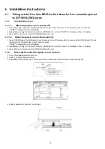
1. Turn off the power, press and hold [OK], [B] and [Y] on the remote control at the same time for more than 5 seconds.
-"00 RET" is displayed on the unit's display.
2. Repeatedly press [ ] on the remote control or [POWER] on the unit until "06 FTO" is displayed on the unit's display.
3. Press [OK] on the remote control or [OPEN/CLOSE] on the unit.
6.1.1.2.
When the power can not be turned off.
1. Press [POWER] key on the front panel for over 4 seconds to turn off the power forcibly, press and hold [OK], [B] and [Y] on the
remote control at the same time for more than 5 seconds.
-"00 RET" is displayed on the unit's display.
2. Repeatedly press [ ] on the remote control or [POWER] on the unit until "06 FTO" is displayed on the unit's display.
3. Press [OK] on the remote control or [OPEN/CLOSE] on the unit.
6.1.2.
When the Forcible Disc Eject can not be done.
1. Turn off the power and pull out AC cord.
2. Put deck so that bottom can be seen.
3. Slide SLIDE CAM by Paper Clip or minus screw driver (small) in the direction of arrow to eject tray slightly.
4. Put deck upward, and pick out Tray by finger.
Summary of Contents for DMR-PWT550GL
Page 2: ...2 ...
Page 3: ...3 ...
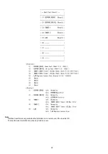
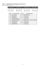
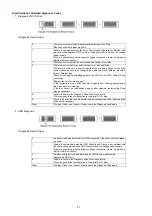
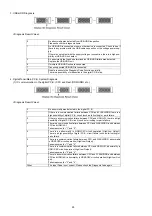
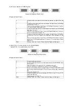
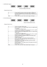
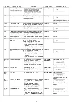
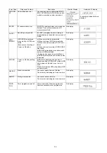
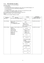
Page 26: ...26 3 10 1 2 Description of the diagnosis code screen Each of the diagnosis code details ...
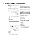
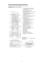
Page 33: ...33 5 Location of Controls and Components ...
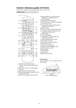
Page 34: ...34 ...
Page 35: ...35 ...
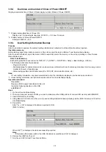
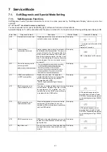
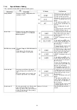
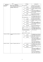
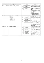
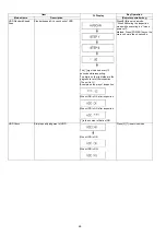
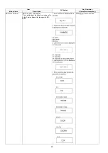
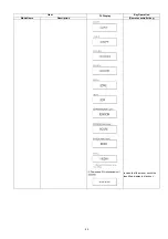
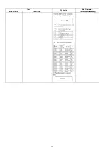
Page 50: ...50 Item FL Display Key Operation Mode Name Description Remote controller key ...
Page 67: ...67 9 11 6 Grease ...
Page 71: ...71 10 1 2 Checking and Repairing of BD Drive ...
Page 72: ...72 10 1 3 Checking and Repairing of Main P C B ...
Page 73: ...73 10 1 4 Checking and Repairing of Digital P C B ...
Page 74: ...74 ...
Page 83: ...Model No DMR PWT550GL GZ SCHEMATIC DIAGRAM NOTICE ...
Page 84: ...Model No DMR PWT550GL GZ PART LIST NOTICE ...
Page 85: ...Model No DMR PWT550GL GZ ABBREVIATION ...
Page 86: ...Model No DMR PWT550GL GZ POWER SECTION POWER P C B ...
Page 87: ...Model No DMR PWT550GL GZ MAIN NET SECTION MAIN P C B ...
Page 88: ...Model No DMR PWT550GL GZ FRONT SW SECTION MAIN P C B ...
Page 89: ...Model No DMR PWT550GL GZ SATA DIGITAL P C B ...
Page 90: ...Model No DMR PWT550GL GZ AUDIO IO SECTION DIGITAL P C B ...
Page 91: ...Model No DMR PWT550GL GZ DDR3 CH 0 SECTION DIGITAL P C B ...
Page 92: ...Model No DMR PWT550GL GZ DDR3 CH 1 SECTION DIGITAL P C B ...
Page 93: ...Model No DMR PWT550GL GZ DEMOD SECTION DEMOD P C B ...
Page 94: ...Model No DMR PWT550GL GZ DIGI NET SECTION DIGITAL P C B ...
Page 95: ...Model No DMR PWT550GL GZ DIGITAL POWER SECTION DIGITAL P C B ...
Page 96: ...Model No DMR PWT550GL GZ ETHER SECTION DIGITAL P C B ...
Page 97: ...Model No DMR PWT550GL GZ EXBUS PERI SECTION DIGITAL P C B ...
Page 98: ...Model No DMR PWT550GL GZ PEAKS PRO4 SECTION DIGITAL P C B ...
Page 99: ...Model No DMR PWT550GL GZ PRO4 POWER SECTION DIGITAL P C B ...
Page 100: ...Model No DMR PWT550GL GZ SATA SD USB SECTION DIGITAL P C B ...
Page 101: ...Model No DMR PWT550GL GZ TIMER SECTION DIGITAL P C B ...
Page 102: ...Model No DMR PWT550GL GZ VIDEO HDMI SECTION DIGITAL P C B ...
Page 103: ...Model No DMR PWT550GL GZ MAIN P C B COMPONENT SIDE ...
Page 104: ...Model No DMR PWT550GL GZ MAIN P C B FOIL SIDE ...
Page 105: ...Model No DMR PWT550GL GZ DIGITAL P C B COMPONENT SIDE ...
Page 106: ...Model No DMR PWT550GL GZ DIGITAL P C B FOIL SIDE ...
Page 107: ...Model No DMR PWT550GL GZ FRONT SW P C B COMPONENT SIDE ...
Page 108: ...Model No DMR PWT550GL GZ FRONT SW P C B FOIL SIDE ...
Page 109: ...Model No DMR PWT550GL GZ SATA P C B COMPONENT SIDE ...
Page 110: ...Model No DMR PWT550GL GZ SATA P C B FOIL SIDE ...
Page 122: ...Model No DMR PWT550GL GZ Exploded View ...
Page 123: ...Model No DMR PWT550GL GZ Mechanism View ...

