23
3.9.2.
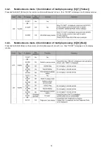
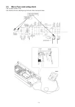
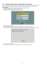
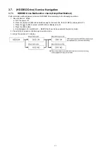
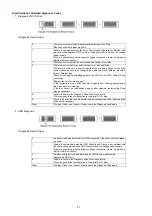
Use times and number of times of Power ON/OFF
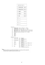
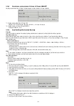
Display accumulated time of Power ON and display number of times of Power ON/OFF.
*1 : Display accumulated time of Power ON
Display on a 15-minute basis. Example: 00123:15
→
123 hour 15 minute
*2 : Display number of times of Power ON/OFF
Example: 0000123
→
123
3.9.3.
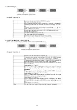
User Setting Information Backup
Purpose
After the recorder is repaired, the restored setting information is not default, but the information before repaired.
Operation summary
Before starting repair, import data on memory of the unit to export the data to USB on Tuner Service Mode display.
After the repair is finished, import the data on USB to export the data to the memory on the unit by operating on Tuner Service.
Mode display again.
•
Data to be backed up
• Each setting item that a user can set at “SET UP” (*1) (START
→
FUNCTION
→
Setup
→
Basic Settings
→
Others.)
The following data cannot be backed up.
- Program chart data
- Dedicated areas for Internet site service providers (unique information for each company), broadcast mail, two-way commu-
nication list, board, or favorite page
- Status saving systems (last channel except for VHF, UHF, drive selection status, etc.)
Note:
Of user setting information, only items selected and set on the initial Setup display can be backed up and restored.
*1: Of user setting information, except items selected and set on the initial Setup display.
Operation procedure
Preparation:
Prepare a USB to export data stored in this unit.
Create the following directory on the USB.
EEPBAKUP
Boot:
1. On Tuner Service Mode display
2. There are many port models of USB, you need to make sure other USB ports don't connect USB memory and USB-HDD.
3. Insert USB memory for writing.
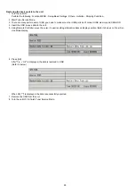
4. Using Remote Controller, move the cursor to useris setting information backup display position (Refer to below) on Tuner Ser-
vice Mode display.
5. Press [OK].
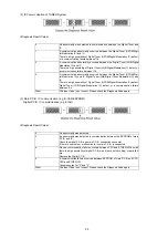
After “Try
→
OK” is displayed, the data is exported to USB.
(Refer to below)
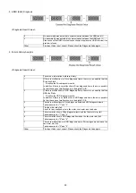
When OK(***) is displayed, the data is successfully exported.
Note:
If the backup file already exists in the USB, the data is overwritten and “OK” is displayed.
6. Remove the USB from the unit.
7. Turn the unit OFF to finish Tuner Service Mode.
Summary of Contents for DMR-PWT550GL
Page 2: ...2 ...
Page 3: ...3 ...
Page 26: ...26 3 10 1 2 Description of the diagnosis code screen Each of the diagnosis code details ...
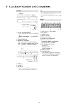
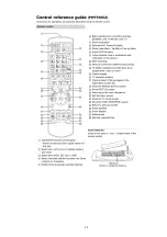
Page 33: ...33 5 Location of Controls and Components ...
Page 34: ...34 ...
Page 35: ...35 ...
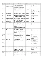
Page 50: ...50 Item FL Display Key Operation Mode Name Description Remote controller key ...
Page 67: ...67 9 11 6 Grease ...
Page 71: ...71 10 1 2 Checking and Repairing of BD Drive ...
Page 72: ...72 10 1 3 Checking and Repairing of Main P C B ...
Page 73: ...73 10 1 4 Checking and Repairing of Digital P C B ...
Page 74: ...74 ...
Page 83: ...Model No DMR PWT550GL GZ SCHEMATIC DIAGRAM NOTICE ...
Page 84: ...Model No DMR PWT550GL GZ PART LIST NOTICE ...
Page 85: ...Model No DMR PWT550GL GZ ABBREVIATION ...
Page 86: ...Model No DMR PWT550GL GZ POWER SECTION POWER P C B ...
Page 87: ...Model No DMR PWT550GL GZ MAIN NET SECTION MAIN P C B ...
Page 88: ...Model No DMR PWT550GL GZ FRONT SW SECTION MAIN P C B ...
Page 89: ...Model No DMR PWT550GL GZ SATA DIGITAL P C B ...
Page 90: ...Model No DMR PWT550GL GZ AUDIO IO SECTION DIGITAL P C B ...
Page 91: ...Model No DMR PWT550GL GZ DDR3 CH 0 SECTION DIGITAL P C B ...
Page 92: ...Model No DMR PWT550GL GZ DDR3 CH 1 SECTION DIGITAL P C B ...
Page 93: ...Model No DMR PWT550GL GZ DEMOD SECTION DEMOD P C B ...
Page 94: ...Model No DMR PWT550GL GZ DIGI NET SECTION DIGITAL P C B ...
Page 95: ...Model No DMR PWT550GL GZ DIGITAL POWER SECTION DIGITAL P C B ...
Page 96: ...Model No DMR PWT550GL GZ ETHER SECTION DIGITAL P C B ...
Page 97: ...Model No DMR PWT550GL GZ EXBUS PERI SECTION DIGITAL P C B ...
Page 98: ...Model No DMR PWT550GL GZ PEAKS PRO4 SECTION DIGITAL P C B ...
Page 99: ...Model No DMR PWT550GL GZ PRO4 POWER SECTION DIGITAL P C B ...
Page 100: ...Model No DMR PWT550GL GZ SATA SD USB SECTION DIGITAL P C B ...
Page 101: ...Model No DMR PWT550GL GZ TIMER SECTION DIGITAL P C B ...
Page 102: ...Model No DMR PWT550GL GZ VIDEO HDMI SECTION DIGITAL P C B ...
Page 103: ...Model No DMR PWT550GL GZ MAIN P C B COMPONENT SIDE ...
Page 104: ...Model No DMR PWT550GL GZ MAIN P C B FOIL SIDE ...
Page 105: ...Model No DMR PWT550GL GZ DIGITAL P C B COMPONENT SIDE ...
Page 106: ...Model No DMR PWT550GL GZ DIGITAL P C B FOIL SIDE ...
Page 107: ...Model No DMR PWT550GL GZ FRONT SW P C B COMPONENT SIDE ...
Page 108: ...Model No DMR PWT550GL GZ FRONT SW P C B FOIL SIDE ...
Page 109: ...Model No DMR PWT550GL GZ SATA P C B COMPONENT SIDE ...
Page 110: ...Model No DMR PWT550GL GZ SATA P C B FOIL SIDE ...
Page 122: ...Model No DMR PWT550GL GZ Exploded View ...
Page 123: ...Model No DMR PWT550GL GZ Mechanism View ...

