16
3.6.
Operation check when a USB device is connected
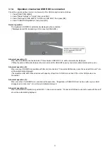
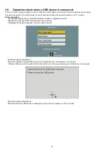
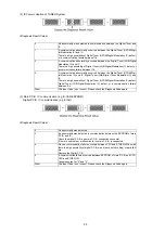
You can check the operation status (normal or abnormal) of the USB connection part of this unit easily as shown below.
Connect each device to the USB terminal on the front panel and check the operation status on the TV monitor.
Normal operation:
Automatically displayed when the USB connection is made to a digital camera, etc.
(Example below: When JPEG materials have been recorded)
(*Displayed items differ depending on the recorded contents.)
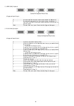
Abnormal operation (Example 1):
Warning is displayed automatically if overcurrent is detected when a USB device is connected.
(*When a USB device or this unitís USB terminal shorts out or the power supply type of USB device is connected)
Abnormal operation (Example 2):
When the terminal of USB device is damaged or open, there is no display on the TV monitor.
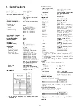
Summary of Contents for DMR-PWT550GL
Page 2: ...2 ...
Page 3: ...3 ...
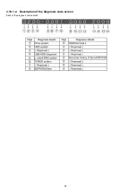
Page 26: ...26 3 10 1 2 Description of the diagnosis code screen Each of the diagnosis code details ...
Page 33: ...33 5 Location of Controls and Components ...
Page 34: ...34 ...
Page 35: ...35 ...
Page 50: ...50 Item FL Display Key Operation Mode Name Description Remote controller key ...
Page 67: ...67 9 11 6 Grease ...
Page 71: ...71 10 1 2 Checking and Repairing of BD Drive ...
Page 72: ...72 10 1 3 Checking and Repairing of Main P C B ...
Page 73: ...73 10 1 4 Checking and Repairing of Digital P C B ...
Page 74: ...74 ...
Page 83: ...Model No DMR PWT550GL GZ SCHEMATIC DIAGRAM NOTICE ...
Page 84: ...Model No DMR PWT550GL GZ PART LIST NOTICE ...
Page 85: ...Model No DMR PWT550GL GZ ABBREVIATION ...
Page 86: ...Model No DMR PWT550GL GZ POWER SECTION POWER P C B ...
Page 87: ...Model No DMR PWT550GL GZ MAIN NET SECTION MAIN P C B ...
Page 88: ...Model No DMR PWT550GL GZ FRONT SW SECTION MAIN P C B ...
Page 89: ...Model No DMR PWT550GL GZ SATA DIGITAL P C B ...
Page 90: ...Model No DMR PWT550GL GZ AUDIO IO SECTION DIGITAL P C B ...
Page 91: ...Model No DMR PWT550GL GZ DDR3 CH 0 SECTION DIGITAL P C B ...
Page 92: ...Model No DMR PWT550GL GZ DDR3 CH 1 SECTION DIGITAL P C B ...
Page 93: ...Model No DMR PWT550GL GZ DEMOD SECTION DEMOD P C B ...
Page 94: ...Model No DMR PWT550GL GZ DIGI NET SECTION DIGITAL P C B ...
Page 95: ...Model No DMR PWT550GL GZ DIGITAL POWER SECTION DIGITAL P C B ...
Page 96: ...Model No DMR PWT550GL GZ ETHER SECTION DIGITAL P C B ...
Page 97: ...Model No DMR PWT550GL GZ EXBUS PERI SECTION DIGITAL P C B ...
Page 98: ...Model No DMR PWT550GL GZ PEAKS PRO4 SECTION DIGITAL P C B ...
Page 99: ...Model No DMR PWT550GL GZ PRO4 POWER SECTION DIGITAL P C B ...
Page 100: ...Model No DMR PWT550GL GZ SATA SD USB SECTION DIGITAL P C B ...
Page 101: ...Model No DMR PWT550GL GZ TIMER SECTION DIGITAL P C B ...
Page 102: ...Model No DMR PWT550GL GZ VIDEO HDMI SECTION DIGITAL P C B ...
Page 103: ...Model No DMR PWT550GL GZ MAIN P C B COMPONENT SIDE ...
Page 104: ...Model No DMR PWT550GL GZ MAIN P C B FOIL SIDE ...
Page 105: ...Model No DMR PWT550GL GZ DIGITAL P C B COMPONENT SIDE ...
Page 106: ...Model No DMR PWT550GL GZ DIGITAL P C B FOIL SIDE ...
Page 107: ...Model No DMR PWT550GL GZ FRONT SW P C B COMPONENT SIDE ...
Page 108: ...Model No DMR PWT550GL GZ FRONT SW P C B FOIL SIDE ...
Page 109: ...Model No DMR PWT550GL GZ SATA P C B COMPONENT SIDE ...
Page 110: ...Model No DMR PWT550GL GZ SATA P C B FOIL SIDE ...
Page 122: ...Model No DMR PWT550GL GZ Exploded View ...
Page 123: ...Model No DMR PWT550GL GZ Mechanism View ...

