42
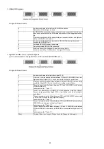
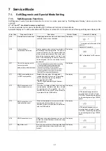
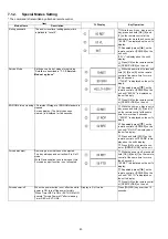
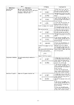
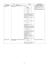
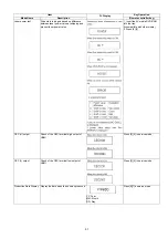
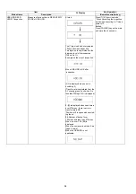
Deep Colour Initialization The Deep Colour setting is initialized.
While the unit is on, press and
hold [OK], [B] and [Y] on the remote
control at the same time for more
than 5 seconds.
-"00 RET" is displayed on the unit's
disply.
Repeatedly press
[
]
on the
remote control or [POWER] on the
unit until "07 DC" is displayed on the
unit's display.
Press and hold [OK] on the
remote control or [OPEN/CLOSE]
on the unit for at least 3 seconds.
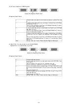
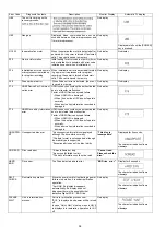
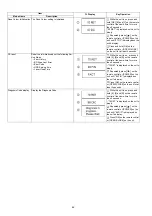
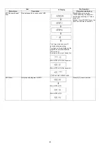
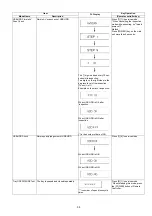
CS reset
Reset the information about the following Ser-
vice Mode.
• Error History
• BD Drive Last Error
• Error Code
• HDD Spin-up time
• Laser Used Time
While the unit is on, press and
hold [5], [9] and [R] on the remote
control at the same time for more
than 5 seconds.
-"70 RET" is displayed on the unit's
disply.
Repeatedly press
[
]
on the
remote control or [POWER] on the
unit until "93 FIN" is displayed on
the unit's display.
Press [OK] on the remote control
or [OPEN/CLOSE] on the unit for at
least 3 seconds.
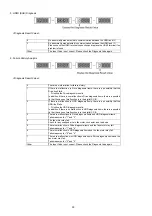
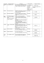
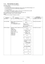
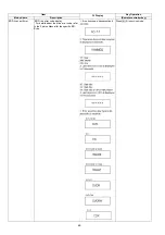
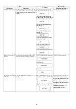
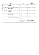
Diagnosis Code display
Display the Diagnosis Code
While the unit is on, press and
hold [5], [9] and [R] on the remote
control at the same time for more
than 5 seconds.
-"70 RET" is displayed on the unit's
disply.
Repeatedly press
[
]
on the
remote control or [POWER] on the
unit until "96 DIC" is displayed on
the unit's display.
Press [OK] on the remote control
or [OPEN/CLOSE] on the unit.
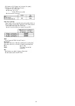
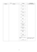
Item
FL Display
Key Operation
Mode Name
Description
Summary of Contents for DMR-PWT550GL
Page 2: ...2 ...
Page 3: ...3 ...
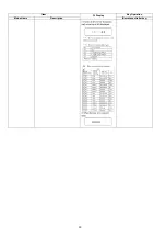
Page 26: ...26 3 10 1 2 Description of the diagnosis code screen Each of the diagnosis code details ...
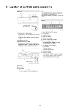
Page 33: ...33 5 Location of Controls and Components ...
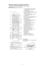
Page 34: ...34 ...
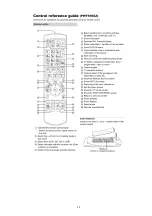
Page 35: ...35 ...
Page 50: ...50 Item FL Display Key Operation Mode Name Description Remote controller key ...
Page 67: ...67 9 11 6 Grease ...
Page 71: ...71 10 1 2 Checking and Repairing of BD Drive ...
Page 72: ...72 10 1 3 Checking and Repairing of Main P C B ...
Page 73: ...73 10 1 4 Checking and Repairing of Digital P C B ...
Page 74: ...74 ...
Page 83: ...Model No DMR PWT550GL GZ SCHEMATIC DIAGRAM NOTICE ...
Page 84: ...Model No DMR PWT550GL GZ PART LIST NOTICE ...
Page 85: ...Model No DMR PWT550GL GZ ABBREVIATION ...
Page 86: ...Model No DMR PWT550GL GZ POWER SECTION POWER P C B ...
Page 87: ...Model No DMR PWT550GL GZ MAIN NET SECTION MAIN P C B ...
Page 88: ...Model No DMR PWT550GL GZ FRONT SW SECTION MAIN P C B ...
Page 89: ...Model No DMR PWT550GL GZ SATA DIGITAL P C B ...
Page 90: ...Model No DMR PWT550GL GZ AUDIO IO SECTION DIGITAL P C B ...
Page 91: ...Model No DMR PWT550GL GZ DDR3 CH 0 SECTION DIGITAL P C B ...
Page 92: ...Model No DMR PWT550GL GZ DDR3 CH 1 SECTION DIGITAL P C B ...
Page 93: ...Model No DMR PWT550GL GZ DEMOD SECTION DEMOD P C B ...
Page 94: ...Model No DMR PWT550GL GZ DIGI NET SECTION DIGITAL P C B ...
Page 95: ...Model No DMR PWT550GL GZ DIGITAL POWER SECTION DIGITAL P C B ...
Page 96: ...Model No DMR PWT550GL GZ ETHER SECTION DIGITAL P C B ...
Page 97: ...Model No DMR PWT550GL GZ EXBUS PERI SECTION DIGITAL P C B ...
Page 98: ...Model No DMR PWT550GL GZ PEAKS PRO4 SECTION DIGITAL P C B ...
Page 99: ...Model No DMR PWT550GL GZ PRO4 POWER SECTION DIGITAL P C B ...
Page 100: ...Model No DMR PWT550GL GZ SATA SD USB SECTION DIGITAL P C B ...
Page 101: ...Model No DMR PWT550GL GZ TIMER SECTION DIGITAL P C B ...
Page 102: ...Model No DMR PWT550GL GZ VIDEO HDMI SECTION DIGITAL P C B ...
Page 103: ...Model No DMR PWT550GL GZ MAIN P C B COMPONENT SIDE ...
Page 104: ...Model No DMR PWT550GL GZ MAIN P C B FOIL SIDE ...
Page 105: ...Model No DMR PWT550GL GZ DIGITAL P C B COMPONENT SIDE ...
Page 106: ...Model No DMR PWT550GL GZ DIGITAL P C B FOIL SIDE ...
Page 107: ...Model No DMR PWT550GL GZ FRONT SW P C B COMPONENT SIDE ...
Page 108: ...Model No DMR PWT550GL GZ FRONT SW P C B FOIL SIDE ...
Page 109: ...Model No DMR PWT550GL GZ SATA P C B COMPONENT SIDE ...
Page 110: ...Model No DMR PWT550GL GZ SATA P C B FOIL SIDE ...
Page 122: ...Model No DMR PWT550GL GZ Exploded View ...
Page 123: ...Model No DMR PWT550GL GZ Mechanism View ...

