54
–
ENGLISH
Adjusting the picture
Switching the picture mode
The user can switch to the desired picture mode
suitable for the image source and the environment in
which this projector is used.
Press
▲▼
to select “PICTURE
1.
MODE”.
PICTURE
PICTURE MODE
CONTRAST
STANDARD
0
Press
◄►
to switch “PICTURE
2.
MODE”.
The setting will change as follows each time
•
◄►
is pressed.
STANDARD
USER
CINEMA
GRAPHIC
NATURAL
DYNAMIC
STANDARD:
•
The picture becomes suitable for moving images in
general.
CINEMA:
•
The picture becomes suitable for movie sources.
NATURAL:
•
The picture complies with sRGB.
DYNAMIC:
•
The picture becomes suitable for the use in well-
lighted areas.
GRAPHIC:
•
The picture becomes suitable for input from to the
personal computer.
USER:
•
The COLOR TEMPERATURE and GAMMA settings
can be adjusted.
Note
Factory defaults are “GRAPHIC” for RGB system
•
and “STANDARD” for moving images.
When ENTER is pressed while “PICTURE MODE”
•
has been selected, the picture mode which has
been selected can be saved and used as the
presetting when new signals are input. The data will
be saved for all items in the PICTURE menu except
for the SYSTEM SELECTOR setting.
Adjusting Contrast
This adjusts the contrast for picture colours.
Press
▲▼
to select
1.
“CONTRAST”.
PICTURE MODE
CONTRAST
BRIGHTNESS
STANDARD
0
0
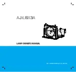
▲▼◄►
ENTER
DEFAULT
MENU
You can adjust pictures to suit your preference.
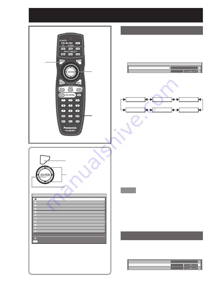
MENU
Press to display the MAIN
MENU screen.
Press to select
“PICTURE”.
Press to display the
“PICTURE” menu.
ENTER
MAIN MENU
PICTURE
POSITION
ADVANCED
MENU
DISPLAY
LANGUAGE
DISPLAY
OPTION
PROJECTOR SETUP
P IN P
TEST
PATTERN
SIGNAL
LIST
SECURITY
NETWORK
MENU
SELECT
SUB MENU
Some menu items may not be valid for certain
•
signal formats applied to the projector.